Azimuth angle domain migration imaging method and system based on complex wave field

A technology of azimuth angle and migration imaging, which is applied in seismic signal processing and other directions, can solve the problems of event crossing and the inability to accurately predict the wave field propagation direction, etc., achieve good resolution of crossing events, and reduce the amount of calculation and storage Effect

Pending Publication Date: 2022-05-06
CHINA PETROLEUM & CHEM CORP +1
View PDF3 Cites 0 Cited by
  • Summary
  • Abstract
  • Description
  • Claims
  • Application Information

AI Technical Summary

Problems solved by technology

Although the shot wave field is relatively simple, it also has event crossing phenomenon caused by multiple arrivals in complex areas, especially in pre-salt areas or areas with strong lateral velocity changes
Decomposing the wave field in local directions, and then using the decomposed wave field to calculate the Poynting vector, this method can alleviate the event crossing problem caused by multiple arrivals to a certain extent, especially at the strong velocity interface, but in In complex areas, wave fields propagating at different angles may propagate in the same direction, making it impossible to accurately predict the direction of wave field propagation when events cross

Method used


Image

  • Azimuth angle domain migration imaging method and system based on complex wave field
  • Azimuth angle domain migration imaging method and system based on complex wave field
  • Azimuth angle domain migration imaging method and system based on complex wave field

Examples


Embodiment 1

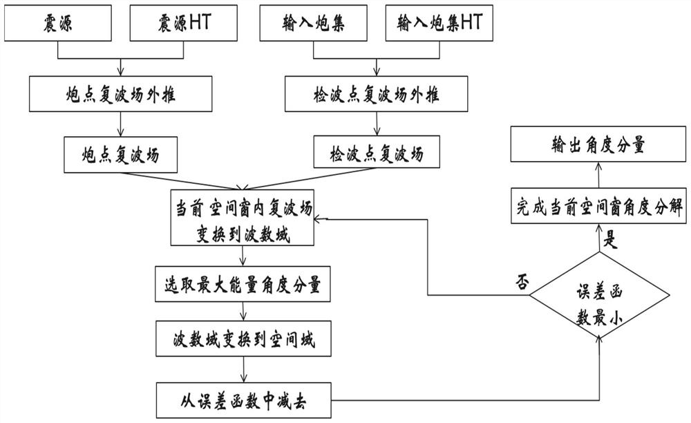
[0093] Such as figure 1 Shown, the inventive method comprises:

[0094] Step 1: Input the source, source HT, shot set, shot set HT, where the input source is a conventional wavelet source, the source HT is the Hilbert transform of the source wavelet, and the shot set HT is the Hilbert transform of the shot set.

[0095] Step 2: Perform extrapolation of the complex wave field of the shot point to obtain the complex wave field of the shot point, and at the same time perform extrapolation of the complex wave field of the detection point to obtain the complex wave field of the detection point (the recorded data of the detection point is the shot set), specifically, use the formula ( 1) The complex wave field of the shot point, using the formula (2) to obtain the complex wave field of the receiver point:

[0096]

[0097]

[0098] Among them, Us and Ur are the wave field at the gun end and the wave field at the receiver end respectively, v is the velocity, t is the time, fs ...

Embodiment 2

[0130] Such as Figure 12 As shown, the system includes:

[0131] The input unit 10 is used to input data: seismic source, seismic source HT, shot set, shot set HT;

[0132] The wave field continuation unit 20 is connected with the input unit 10, and is used for extrapolating the complex wave field of the shot point to obtain the complex wave field of the shot point, and at the same time performing the extrapolation of the complex wave field of the detection point to obtain the complex wave field of the detection point;

[0133] The angle component acquisition unit 30 is connected with the wave field extension unit 20, and is used to decompose the complex wave field of the shot point and the complex wave field of the receiver point into a plurality of identical spatial windows, and then obtain all angles of each spatial window weight;

[0134] The imaging unit 40 is connected with the angle component acquisition unit 30, and is configured to obtain an azimuth domain imaging ...

Embodiment 3

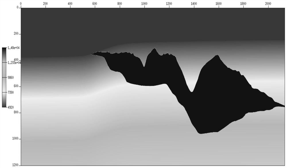
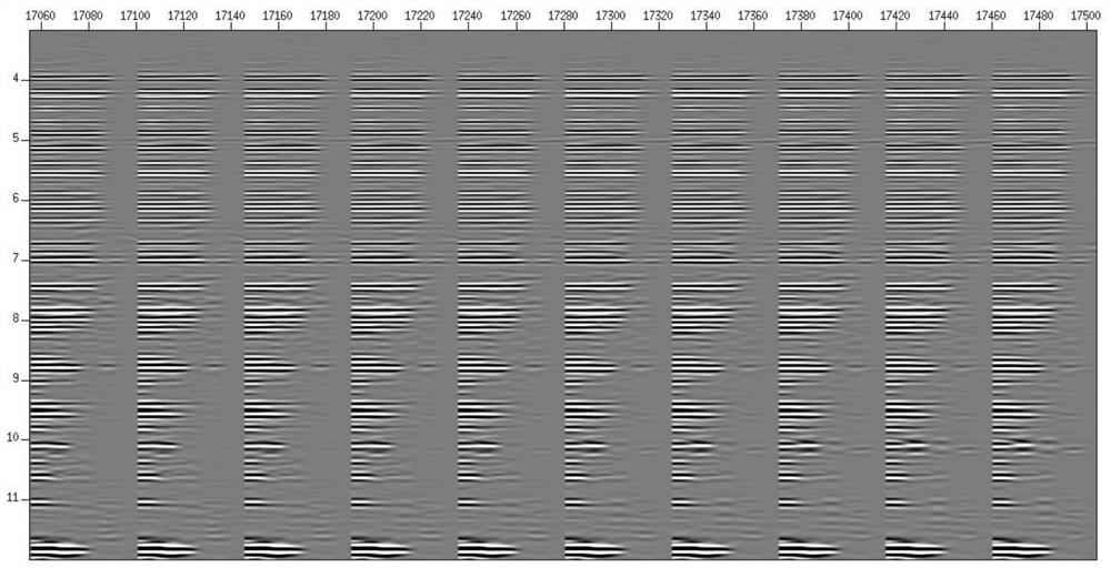
[0137] In order to verify the correctness and adaptability of the algorithm, the algorithm test was carried out on the two-dimensional Sigsbee2a theoretical model, figure 2 is the theoretical velocity model, image 3 with Figure 4 The local angle gathers are extracted for regions with simple structures and complex structures. The range of angle gathers is 0-60 degrees, and the interval is 2 degrees. The final stacked profile of all angle gathers is as follows Figure 5 As shown, the imaging quality of the obtained stacked migration section is comparable to the imaging result directly output by conventional RTM, and because the maximum angle is 60 degrees, the low-frequency imaging noise in the stacked imaging section is basically removed.


PUM


Abstract

The invention provides an azimuth angle domain migration imaging method and system based on a complex wave field, and belongs to the field of seismic migration imaging. According to the azimuth angle domain migration imaging method based on the complex wave field, the complex wave field continuation of a shot point wave field and a detection point wave field is firstly carried out, then the local angle decomposition of the complex wave field is realized in each space window to obtain the local angle components of the shot point wave field and the detection point wave field, and finally, the angle domain gathers of different azimuths are superposed to obtain the azimuth angle domain migration imaging of the shot point wave field and the detection point wave field. And obtaining a final azimuth angle domain imaging result. The azimuth angle domain imaging gather obtained through the method has the good cross event distinguishing capacity, underground structure information can be truly reflected, meanwhile, the calculation amount and the storage amount are reduced, and a powerful tool is provided for seismic data processing and seismic data quantitative interpretation in a complex area.

Description

technical field [0001] The invention belongs to the field of seismic migration imaging, in particular to an azimuth angle domain migration imaging method and system based on a complex wave field. Background technique [0002] Migration velocity modeling is the core step of seismic processing. A high-quality migration velocity model is a key factor for producing high-quality subsurface imaging results. Amplitude versus offset analysis (AVO) and amplitude versus angle analysis (AVA) are It is a key step in seismic processing and quantitative interpretation of seismic data. It can convert migrated seismic data into subsurface rock parameter information to guide oil and gas exploration. These two key steps in seismic data analysis require migration imaging gathers as their input, so high-quality migration imaging gathers can effectively reduce the risk of seismic exploration. The azimuth-angle domain migration imaging gather based on the subsurface parameter index is less affec...

Claims


Application Information

Patent Timeline
IPC IPC(8): G01V1/28
CPCG01V1/28
Inventor 许璐李博吕庆达
Owner CHINA PETROLEUM & CHEM CORP
Why Eureka
Try Eureka