Limb bearing frame for medical care
A technology of bearing brackets and limbs, applied in the field of bearing brackets, can solve the problems of inability to raise both legs, small applicability, poor fixing effect, etc., and achieve the effect of convenient and effective nursing and improving work efficiency.
- Summary
- Abstract
- Description
- Claims
- Application Information
AI Technical Summary
Problems solved by technology
Method used
Image
Examples
Embodiment 1
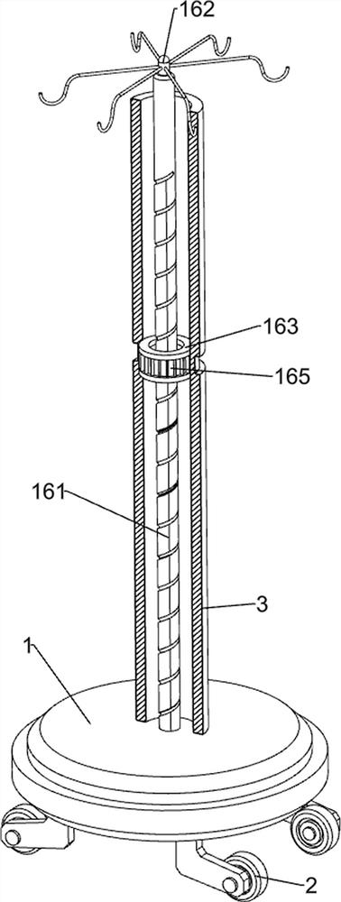
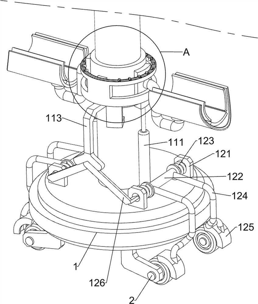
[0034] A limb support bracket for medical care, please refer to Figure 1 to Figure 5, including base 1, roller 2, support column 3, first connecting frame 4, slider 41, first connecting rod 5, pallet 6, first spring 7, clamping plate 8, second spring 9, block 10. The lifting mechanism 11 and the limiting mechanism 12, the four corners of the bottom of the base 1 are rotatably connected to the rollers 2, the middle of the top of the base 1 is connected to the support column 3 by welding, and the lower part of the outer wall of the support column 3 slides The first connecting frame 4 is connected, and the left and right sides of the inner wall of the first connecting frame 4 are slidably connected with sliders 41, and the sides of the two sliders 41 away from each other are connected with the first connecting rod 5 by welding , the tops of the two first connecting rods 5 are rotatably connected with a supporting plate 6, the supporting plate 6 is used to support the affected li...
Embodiment 2
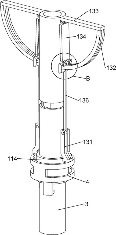
[0039] On the basis of Example 1, please refer to figure 1 , Figure 5 and Figure 6 , also includes an opening and closing mechanism 13, the opening and closing mechanism 13 includes a first fixed rod 131, a slide rail 132, a first fixed plate 133, a lighting lamp 134, a second connecting frame 135 and a third connecting rod 136, and the fixing cylinder 114 The left and right sides of the top are connected with the first fixed rod 131 by welding, the left and right sides of the outer wall top of the support column 3 are connected with the first fixed plate 133 by welding, and the bottoms of the two first fixed plates 133 are far away from each other. A slide rail 132 is connected between one side of the support column 3 and the support column 3 by welding, and the slide rail 132 is used to fix the lighting lamp 134. Illuminating lamp 134, illuminating lamp 134 is used for illuminating the affected limb when the medical staff is working, the bottom of illuminating lamp 134 i...
Embodiment 3
[0042] On the basis of Example 2, please refer to figure 1 , Figure 7 , Figure 8 and Figure 9 , also includes a fixing mechanism 14, the fixing mechanism 14 includes a second fixing rod 141, a first fixing ring 142, a first sliding rod 143, a second sliding rod 144, a fourth connecting rod 145, a magnetic plate 146 and a sponge pad 147, the front and rear sides of the upper part of the outer wall of the support column 3 are connected with the second fixed rod 141 by welding, and the first fixed ring 142 is connected by welding between the sides of the two second fixed rods 141 that are far away from each other. The front and rear sides on the right side of the first fixed ring 142 are slidably connected with the first sliding rod 143, and the insides of the two first sliding rods 143 are slidably connected with the second sliding rod 144. The bottoms of the rods 144 are rotatably connected with a fourth connecting rod 145, the fourth connecting rod 145 is used to fix the...
PUM
 Abstract
Description
Claims
Application Information
 - R&D
- Intellectual Property
- Life Sciences
- Materials
- Tech Scout
- Unparalleled Data Quality
- Higher Quality Content
- 60% Fewer Hallucinations
Browse by: Latest US Patents, China's latest patents, Technical Efficacy Thesaurus, Application Domain, Technology Topic, Popular Technical Reports.
© 2025 PatSnap. All rights reserved.Legal|Privacy policy|Modern Slavery Act Transparency Statement|Sitemap|About US| Contact US: help@patsnap.com


