Art knife

A utility knife and blade technology, which is applied in the field of utility knives, can solve the problems of inability to achieve infinite adjustment, troublesome, and unaffected by users.

Pending Publication Date: 2022-05-10
DELI GROUP CO LTD
View PDF0 Cites 1 Cited by
  • Summary
  • Abstract
  • Description
  • Claims
  • Application Information

AI Technical Summary

Problems solved by technology

[0003] In the prior art, the way to lock the blade body is to respectively set a card slot and a buckle on the connecting part of the protective shell and the blade, and the buckle and the card slot are connected by pressing or pushing, and several card slots are generally provided. The buckle is connected with different slots to adjust the length of the blade protruding from the protective shell. This method is restricted by the position of the slot and cannot be adjusted steplessly. Moreover, when the buckle and the slot are connected together, there will be a snapping sound, which is not Mute adjustment
There is also a method of locking the knife body by thread locking, that is, after adjusting the length of the knife body protruding from the protective case, press the knife body with screws or studs. Before and after use, it is necessary to lock and release the blade by rotating the thread, which is really troublesome and not very popular with users

Method used


Image

  • Art knife
  • Art knife
  • Art knife

Examples


Embodiment 1

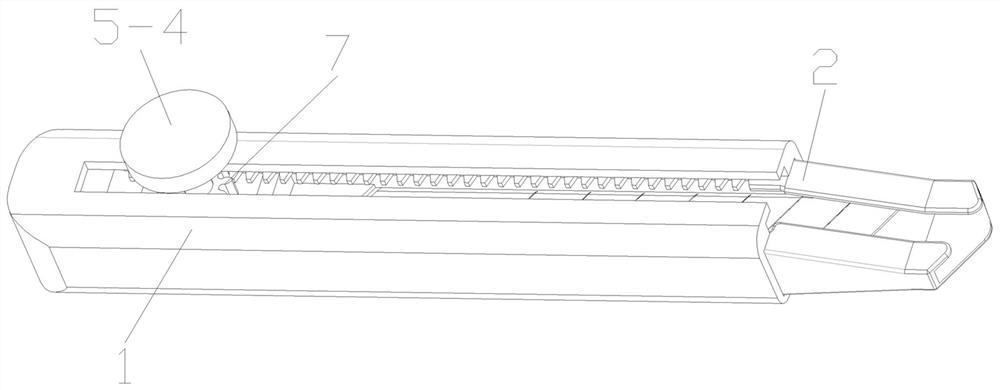
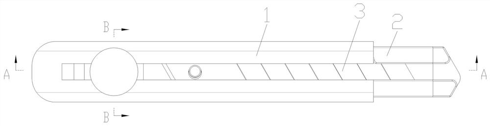
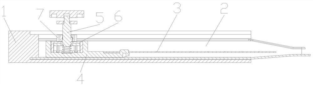
[0027] Such as Figure 1 to Figure 6 As shown in , the utility knife of the present invention includes a protective case 1, a bushing 2, a slider 4, a blade 3, a gear mounting part 5, a limit block 6 and a gear 7, the bushing 2 is arranged in the protective case 1, and the bushing 2 is provided with a chute 2-1, a side of the chute 2-1 along the length direction is provided with a rack 2-2, the slider 4 is slidably arranged in the chute 2-1, and the blade 3 is arranged on the On the slider 4, the bushing 2 is provided with a blocking portion 2-3 and a knife edge 2-4 at one end of the chute 2-1, the slider 4 drives the blade 3 to slide so that the blade 3 protrudes out of the knife edge 2-4, When the slider 4 moves to contact with the blocking portion 2-3, the blocking portion 2-3 limits the slider 4, and at this time the length of the blade 3 protruding out of the knife edge 2-4 is the largest.

[0028] The gear mounting part 5 is integrally formed with a gear shaft 5-3 and f...

Embodiment 2

[0033] The difference between the utility knife of this embodiment and Embodiment 1 is that the second limit structure of the slider 4 to the circumferential limit of the gear mounting part 5 is different. In this embodiment, the gear mounting part 5 is provided with a bayonet, and the sliding The block 4 is provided with a detachable buckle head that cooperates with the buckle, and the shaft cap 5-4 is pulled upward to make the gear mounting part 5 rise, so that the bayonet and the buckle head are buckled and connected, and the slider 4 is connected to the gear. The mounting part 5 is limited in the circumferential direction, and the gear mounting part 5 is lowered by pressing the shaft cap 5-4, so that the bayonet can be disengaged from the buckle, and the slide block 4 cannot limit the gear mounting part 5 in the circumferential direction.

[0034] Since the gear mounting part 5 and the gear shaft 5-3 are integrally formed, it can be understood that the lifting of the gear m...


PUM


Abstract

The invention provides an art knife which comprises a protective shell, a blade and a sliding block, the sliding block is arranged in the protective shell in a sliding mode, the blade is arranged on the sliding block, a liftable gear shaft is arranged on the sliding block, the gear shaft can drive the sliding block to drive the blade to slide, a gear is arranged on the gear shaft, and a rack is arranged on the protective shell. The gear is limited above the sliding block and meshed with the rack, a first limiting structure and a second limiting structure are arranged on the gear shaft, the first limiting structure is used for being in contact with the gear and circumferentially limiting the gear, and the second limiting structure is used for being in contact with the sliding block and enabling the sliding block to circumferentially limit the gear shaft; after the gear shaft ascends, the first limiting structure and the second limiting structure can make contact with the gear and the sliding block correspondingly at the same time. And after the gear shaft descends, the first limiting structure can be separated from the gear, so that the gear can rotate around the gear shaft. According to the art knife, the length of the knife body extending out of the protective shell can be steplessly adjusted, the adjusting process is silent, and operation is very convenient.

Description

technical field [0001] The present invention relates to the technical field of manual cutting tools, more specifically to a utility knife. Background technique [0002] In the prior art, the blades of utility knives are mostly beveled, and there are several scribed lines parallel to the blades on the body. If the blade becomes blunt or collapsed, the nearest scribed line can be broken to produce a new blade. Therefore, the blade is shortened; the blade of the utility knife is still very brittle, and the blade should not be too long when used, otherwise it will be easily broken. In order to make utility knives with different blade lengths can be used normally, generally the utility knife is set in the protective case, and when in use, the blade is pushed out of the protective case to an appropriate length and locked and kept. In this way, the length of the blade in use is extended The length of the protective case can be adjusted at will. [0003] In the prior art, the way ...

Claims


Application Information

Patent Timeline
IPC IPC(8): B26B1/08
CPCB26B1/08
Inventor 王奎吴潇雄
Owner DELI GROUP CO LTD
Why Eureka
Try Eureka