
Piston type pneumatic motor for emergency rescue

An emergency rescue, air motor technology, applied in the direction of engine components, machines/engines, mechanical equipment, etc., can solve the problems of poor service life, affecting the rescue effect, poor motor stability, etc., to increase the stability of use, improve the use of Safety and the effect of improving the service life

Inactive Publication Date: 2022-05-10
如东宏信机械制造有限公司
View PDF0 Cites 0 Cited by
  • Summary
  • Abstract
  • Description
  • Claims
  • Application Information

AI Technical Summary

Problems solved by technology

[0004] The purpose of the present invention is to provide a piston-type air motor for emergency rescue, which has the advantage of high stability in use, and solves the problem that the drive shaft of the existing device continues to rotate under the action of inertia after the air intake is closed, and cannot be stopped immediately, which affects the The rescue effect during rescue is poor in use safety, and the piston air motor has a large vibration force during operation, which cannot be buffered, poor stability of the motor, and poor service life.

Method used


Image

  • Piston type pneumatic motor for emergency rescue
  • Piston type pneumatic motor for emergency rescue
  • Piston type pneumatic motor for emergency rescue

Examples


Embodiment 1

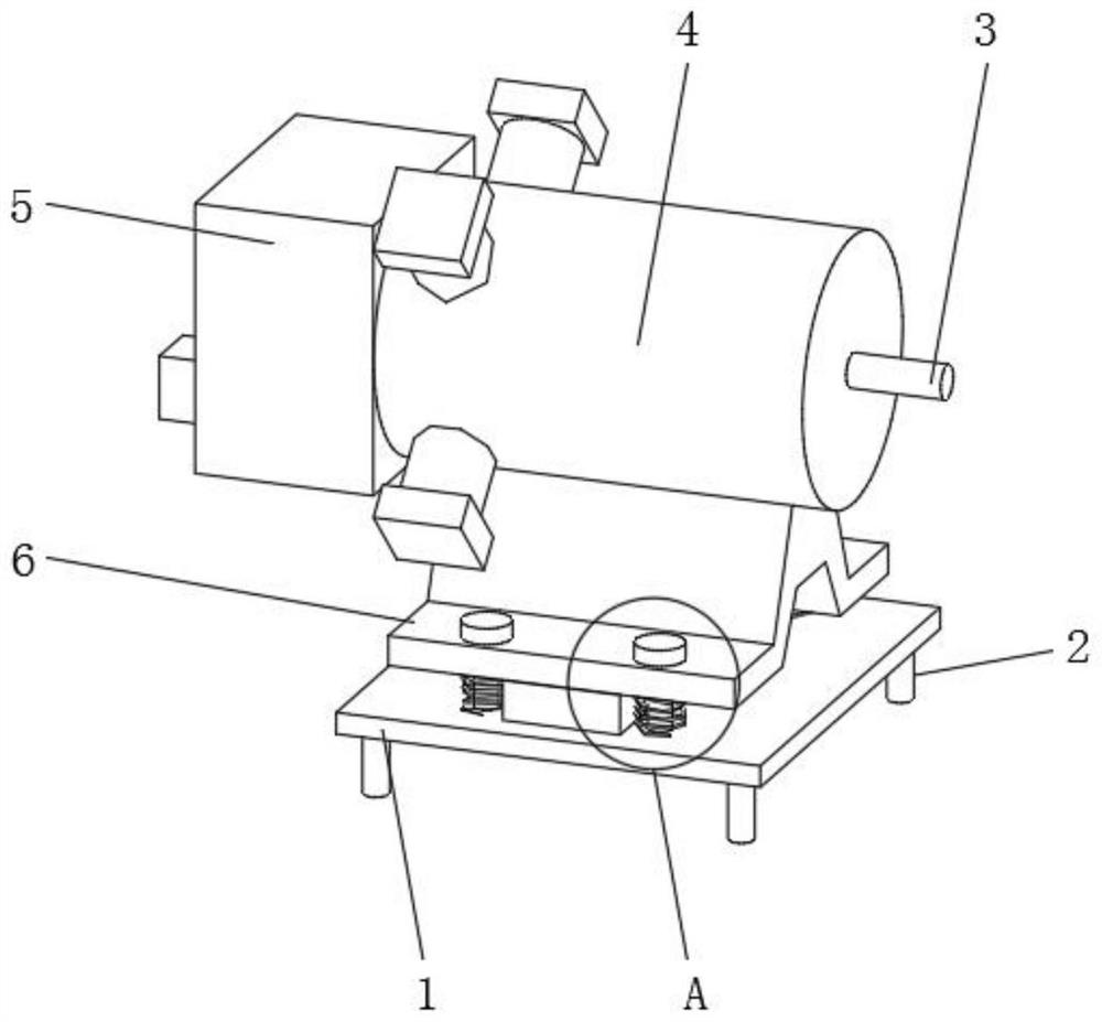
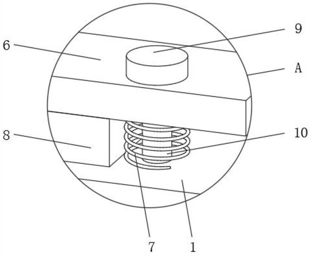
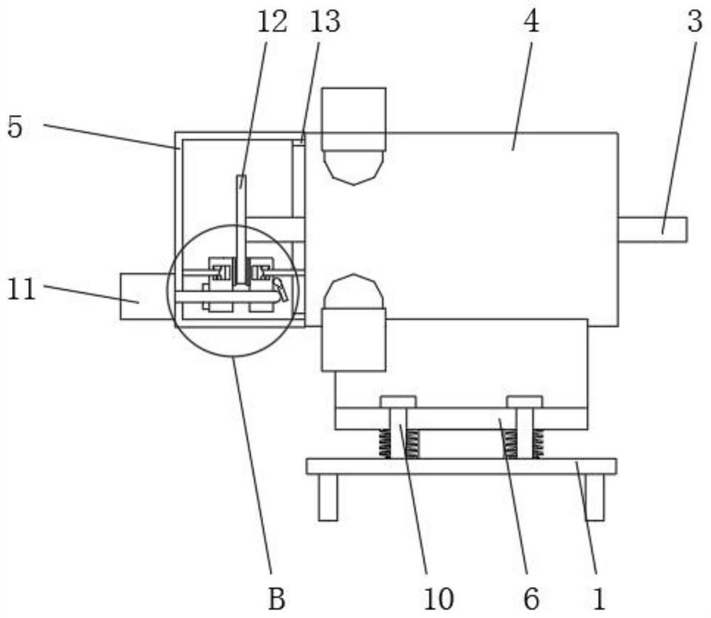
[0023] Such as Figure 1-4 As shown, in order to achieve the above object, the present invention provides the following technical solutions: a piston type air motor for emergency rescue, including a fixed seat 1 and a main body 4, buffer columns 10 are installed at the top four corners of the fixed seat 1, and the buffer column The outer surface of 10 is located on the top of the fixed seat 1, and the supporting seat 6 is installed. The main body 4 is installed on the top of the supporting seat 6, and the drive shaft 3 is installed in the middle of the main body 4. The outer surface of the buffer column 10 is located at the gap between the supporting seat 6 and the base. The spring 7, the top of the buffer column 10 is located on the upper surface of the support seat 6, and the spring seat 9 is installed on the upper surface. The rear cover 5 is installed on the side of the main body 4 through the connecting seat 13. One end of the drive shaft 3 is located inside the rear cover...

Embodiment 2

[0026] Such as Figure 1-4 As shown, the present invention proposes a piston-type air motor for emergency rescue. Compared with Embodiment 1, this embodiment also includes: the top of the fixing seat 1 near the middle of the front surface and the middle of the rear surface are equipped with rubber Seat 8, fixed column 2 is all installed at four corner positions of the bottom of fixed seat 1.

[0027] In this embodiment, before use, the present invention is quickly fixed by the fixing column 2. During use, the rubber seat 8 and the buffer spring 7 are used to buffer the vibration force of the main body 4 to increase the stability of the present invention.


PUM


Abstract

The invention relates to the technical field of pneumatic motors, in particular to a piston type pneumatic motor for emergency rescue. According to the technical scheme, the device comprises a fixing seat and a body, buffer columns are installed at the four corners of the top of the fixing seat, a supporting seat is installed on the outer surfaces of the buffer columns and located on the top of the fixing seat, the body is installed on the top of the supporting seat, and a driving shaft is installed in the middle of the interior of the body; buffering springs are installed on the outer surfaces of the buffering columns and located at the gap positions of the supporting seat and the base, and spring seats are installed on the tops of the buffering columns and located on the upper surface of the supporting seat. The problems that a driving shaft of an existing device continuously rotates under the inertia effect after air inlet is closed, the driving shaft cannot be stopped immediately, the rescue effect during rescue is affected, the use safety is poor, a piston type pneumatic motor is large in vibration force in the operation process, the piston type pneumatic motor cannot be buffered, and the use stability of the motor is poor are solved. And the stop speed of the driving shaft is increased, so that the use safety of the pneumatic motor is improved.

Description

technical field [0001] The invention relates to the technical field of air motors, in particular to a piston-type air motor for emergency rescue. Background technique [0002] Pneumatic motors, also known as wind motors, refer to devices that convert the pressure energy of compressed air into rotational mechanical energy. Generally used as a source of rotational power for more complex devices or machines. According to the structure, air motors are classified into: vane air motors, piston air motors, compact vane air motors, and compact piston air motors. Air motors are devices that convert the pressure energy of compressed air into rotational mechanical energy. Its function is equivalent to that of an electric motor or a hydraulic motor, that is, the output torque is used to rotate the drive mechanism. [0003] In the existing air motor, the drive shaft continues to rotate under the action of inertia after the air intake is closed, and it cannot be stopped immediately, whi...

Claims


Application Information

Patent Timeline
Patent Type & Authority Applications(China)
IPC IPC(8): F01B31/00
CPCF01B31/00
Inventor 缪煜
Owner 如东宏信机械制造有限公司
Learn More