
Pipeline small defect axial length detection method and application thereof

A technology of axial length and detection method, which is applied in the processing of detection response signals, measuring devices, and the use of sound waves/ultrasonic waves/infrasonic waves to analyze solids, etc. It can solve difficult to extract defect signals, local optimal and global convergence probability of differential evolution algorithm Low-level problems, to achieve fast propagation speed, realize the health status assessment of pipeline ultrasonic guided wave detection and diagnosis, and solve the effect of quantitative identification problems

Pending Publication Date: 2022-05-10
NAVAL UNIV OF ENG PLA
View PDF0 Cites 0 Cited by
  • Summary
  • Abstract
  • Description
  • Claims
  • Application Information

AI Technical Summary

Problems solved by technology

Large defects can be decomposed into front and rear reflection signals by traditional matching pursuit algorithm. However, when the size of the defect is small and the noise is large, it is difficult for these conventional signal processing methods to quickly extract the defect signal. In the prior art, it is proposed to use differential Evolutionary Algorithm Improves Matching Pursuit Method to Extract Guided Wave Signal
However, the differential evolution algorithm has the disadvantages that it is easy to fall into local optimum and the global convergence probability is low

Method used


Image

  • Pipeline small defect axial length detection method and application thereof
  • Pipeline small defect axial length detection method and application thereof
  • Pipeline small defect axial length detection method and application thereof

Examples


Embodiment Construction

[0049]In order to make the object, technical solution and advantages of the present invention clearer, the present invention will be further described in detail below in conjunction with the accompanying drawings and embodiments. It should be understood that the specific embodiments described here are only used to explain the present invention, not to limit the present invention. In addition, the technical features involved in the various embodiments of the present invention described below can be combined with each other as long as they do not constitute a conflict with each other.

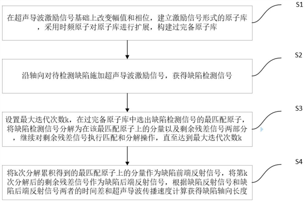
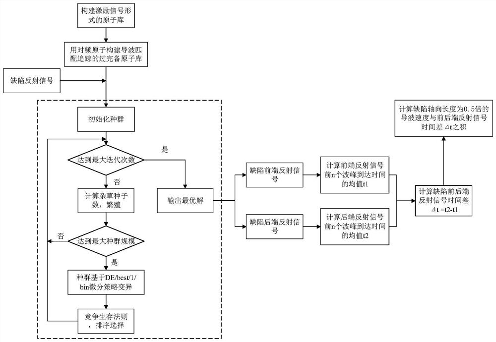
[0050] Such as figure 1 As shown, a method for detecting the axial length of a small pipeline defect in an embodiment of the present invention includes steps:

[0051] S1, change the amplitude and phase on the basis of the ultrasonic guided wave excitation signal, establish an atomic library in the form of the excitation signal, expand the atomic library by using time-frequency atoms, and constr...


PUM


Abstract

The invention discloses a method for detecting the axial length of a small defect of a pipeline and application of the method. According to the method, on the basis of analyzing the reflection characteristics of ultrasonic guided wave pipeline detection defect signals, an over-complete atom library is established, atoms which are most matched with to-be-decomposed signals are selected from the over-complete atom library, the signals can be decomposed into components and residual errors on the optimal atoms, the remaining residual error parts continue to be decomposed until the end conditions are met, and finally, the detection defect signals are obtained. The axial length of the defect can be obtained by calculating the product of the time difference of the front-end reflection signal and the rear-end reflection signal and the propagation speed of the ultrasonic guided wave in the pipeline. In the calculation process, due to the fact that the capacity of an over-complete atom library is large, the calculation workload is large, and convergence is slow, the improved matching pursuit algorithm is adopted for optimizing and solving, the calculation speed can be increased, the axial length of small defects can be quantitatively measured, and pipeline ultrasonic guided wave detection and diagnosis health state evaluation can be achieved.

Description

technical field [0001] The invention belongs to the technical field of non-destructive testing, and more specifically relates to a method for detecting the axial length of small defects in pipelines and its application. Background technique [0002] Ultrasonic guided wave testing technology has been widely used in non-destructive testing, and has broad application prospects because of its advantages such as fast, long-distance, and large-scale testing. However, the guided wave detection signal often contains various noises, which affect the identification and location of the defect signal. Therefore, it is a difficult problem in the guided wave nondestructive testing technology to extract valuable signals from the noisy guided wave signal. [0003] Commonly used guided wave signal processing methods include short-time Fourier transform, wavelet transform, time-frequency analysis, spectrum analysis and correlation analysis. Large defects can be decomposed into front and rear...

Claims


Application Information

Patent Timeline
IPC IPC(8): G01N29/44G01N29/06
CPCG01N29/4472G01N29/069G01N2291/0289
Inventor 王悦民陈昂汤槟晖邱增城许鉴鉴
Owner NAVAL UNIV OF ENG PLA
Learn More