
Optical processing device for non-contact human body posture acquisition

A technology of human body posture and optical processing, applied in optics, application, medical science, etc., can solve the problems of poor camera concealment, manual adjustment of the camera, etc., and achieve the effect of expanding the range

Pending Publication Date: 2022-05-10
江伟伟
View PDF0 Cites 0 Cited by
  • Summary
  • Abstract
  • Description
  • Claims
  • Application Information

AI Technical Summary

Problems solved by technology

[0005] In order to overcome the disadvantages of the existing optical processing device for human body posture acquisition, which have poor camera concealment and need to manually adjust the angle of the camera, the technical problem to be solved is to provide a camera that can automatically rotate towards the human body when someone enters, and the camera Stealthy Optical Processing Device for Non-contact Human Body Pose Acquisition

Method used


Image

  • Optical processing device for non-contact human body posture acquisition
  • Optical processing device for non-contact human body posture acquisition
  • Optical processing device for non-contact human body posture acquisition

Examples


Embodiment 1

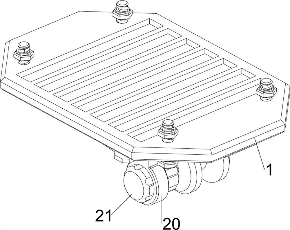
[0037] An optical processing device for non-contact human body posture acquisition, such as Figure 1-8 As shown, it includes a first fixed plate 1, a fixed plate 11, a rotating shaft 12, a camera 13, a fixed bolt 14, a turning mechanism 2 and a dehumidification mechanism 3, and the left and right sides of the first fixed plate 1 are connected with fixed Bolt 14, the first fixed plate 1 can be fixed on the ceiling by the fixed bolt 14, the left and right sides of the front side of the bottom of the first fixed plate 1 are all provided with fixed disks 11 by bolts, and the rotating shafts are connected between the fixed disks 11 12. The middle part of the rotating shaft 12 is provided with a camera 13 for taking pictures of human body postures. The rear part of the camera 13 is a camera.

[0038] Such as Figure 5 and Figure 6 As shown, the turnover mechanism 2 includes a connecting ring 20, a first servo motor 21, a mounting block 22 and a distance sensor 23. The left front...

Embodiment 2

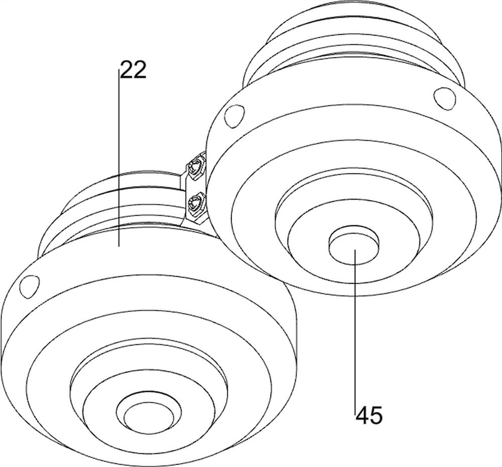
[0042] On the basis of Example 1, such as figure 1 , figure 2 , Figure 9 and Figure 10 As shown, it also includes a wide-angle adjustment mechanism 4, which can adjust the wide-angle of the camera. The wide-angle adjustment mechanism 4 arc-shaped plate 40, the second servo motor 41, the turret 42, the common lens 43, the wide-angle lens 44 and the temperature sensor 45, cover An arc plate 40 is welded on the left side of the ring 30, a second servo motor 41 is provided by bolts in the arc plate 40, a turret 42 is provided on the rear side of the output shaft of the second servo motor 41, and the output shaft of the second servo motor 41 can rotate Drive the turret 42 to rotate, the upper right side of the turret 42 is provided with a common lens 43 through a bolt, the common lens 43 is positioned at the rear side of the camera, the lower right part of the turret 42 is provided with a wide-angle lens 44 through a bolt, and the left side of the mounting block 22 bottom is p...


PUM


Abstract

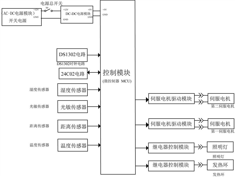
The invention relates to an optical processing device for acquiring a human body posture, in particular to an optical processing device for acquiring a non-contact human body posture. The technical problem to be solved is to provide the optical processing device for acquiring the non-contact human body posture, which can realize that a camera automatically rotates to face a human body when a person enters the device, and the camera has secrecy. An optical processing device for non-contact human body posture acquisition comprises a first fixing plate, fixing discs, a rotating shaft, a shooting device, fixing bolts and the like, the left side and the right side of the first fixing plate are both in threaded connection with the fixing bolts in a front-back symmetrical mode, the left side and the right side of the front side of the bottom of the first fixing plate are both provided with the fixing discs, and the rotating shaft is rotationally connected between the fixing discs. Under the detection effect of the humidity sensor, the heating ring can heat and dry the camera of the camera, so that the dehumidification effect can be achieved, and the damp-proof effect is achieved.

Description

technical field [0001] The invention relates to an optical processing device for obtaining human body posture, in particular to an optical processing device for non-contact human body posture obtaining. Background technique [0002] Currently, cameras are generally used to obtain human body postures. There are various existing cameras, including fixed ones and portable ones. However, fixed cameras are generally used in confidential places. , to fix the camera on the ceiling. [0003] The existing optical processing device for human body posture acquisition includes a first fixed plate, a fixed plate, a rotating shaft, a camera, and a fixed bolt. The left and right sides of the first fixed plate are connected with the fixed bolts in a symmetrical threaded manner, and the fixed bolts can be connected The first fixed plate is fixed on the ceiling, and the left and right sides of the front side of the bottom of the first fixed plate are provided with fixed plates through bolts,...

Claims


Application Information

Patent Timeline
Patent Type & Authority Applications(China)
IPC IPC(8): H04N5/225H04N5/232G03B17/55A61B5/00A61B5/11F16M11/10F16M11/18F16M13/02
CPCG03B17/55A61B5/1116A61B5/1128A61B5/0077F16M13/027F16M11/10F16M11/18H04N23/56H04N23/50H04N23/55H04N23/65
Inventor 江伟伟
Owner 江伟伟
Learn More