Device for improving combustion efficiency of boiler by reducing moisture content of air

A boiler combustion and moisture content technology, applied in gas treatment, separation methods, dispersed particle separation, etc., can solve the problems of complex regeneration system and lower equipment working efficiency, and achieve simple regeneration system, reduced strength, and reduced noise pollution Effect

Pending Publication Date: 2022-06-17
河南京能滑州热电有限责任公司
View PDF8 Cites 0 Cited by
  • Summary
  • Abstract
  • Description
  • Claims
  • Application Information

AI Technical Summary

Problems solved by technology

[0009] The purpose of the present invention is to provide a device that reduces the moisture content of the air to improve the combustion efficiency of the boiler, so as to solve the problem tha

Method used


Image

  • Device for improving combustion efficiency of boiler by reducing moisture content of air
  • Device for improving combustion efficiency of boiler by reducing moisture content of air
  • Device for improving combustion efficiency of boiler by reducing moisture content of air

Examples


Example Embodiment

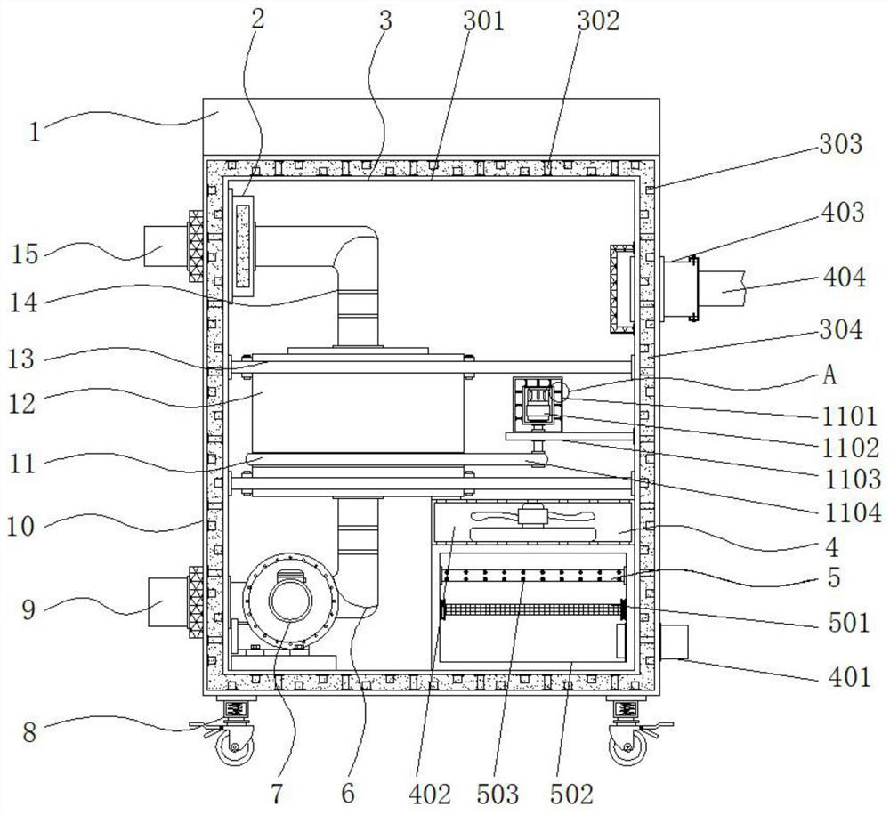
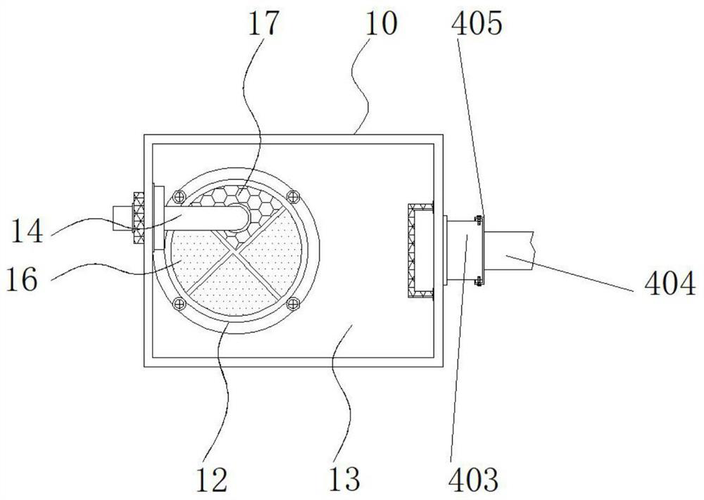
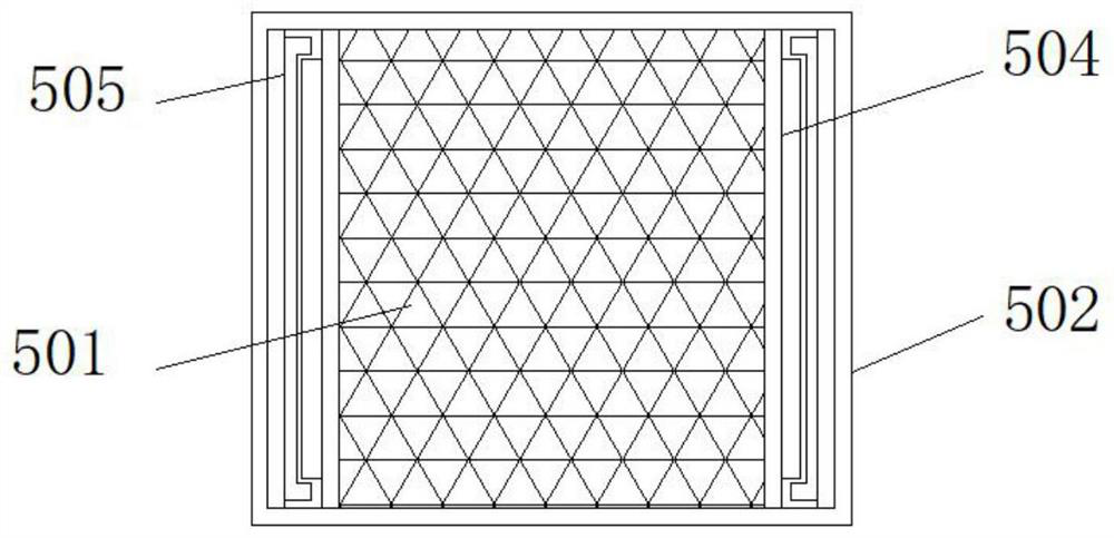
[0035]实施例1:请参阅图1-6,一种降低空气含湿量来提高锅炉燃烧效率的装置,包括设备主体10,设备主体10的顶端固定连接有顶板1,设备主体10底端的两侧固定连接有移动轮8,设备主体10的内壁上设置有隔音降噪结构3,设备主体10内部的顶端横向固定连接有横板13,横板13之间的一侧设置有转轮12,转轮12内部的一侧设置有吸湿区16,转轮12内部的另一侧设置有再生区17,转轮12的外部设置有传动机构11,设备主体10内部底端的一侧设置有净化结构5,净化结构5的上方设置有送风机构4,转轮12的顶端以及底端设置有再生机构;

[0036]请参阅图1-6,一种降低空气含湿量来提高锅炉燃烧效率的装置还包括再生机构,再生机构包括第二出风口9,第二出风口9固定连接在设备主体10一侧的底端,第二出风口9的一侧与下导风管6的内部连通,下导风管6底端的一侧设置有第二风机7,该第二风机7的型号可为HTF,下导风管6的顶端与再生区17的内部连通,再生区17的顶部固定连接有上导风管14,上导风管14的顶端设置有加热器2,该加热器2的型号可为HVL031-300W,加热器2固定连接在设备主体10内部顶端的一侧,上导风管14的内部与第二进风口15的内部连通;

[0037]吸湿区16的内部设置有多组硅胶孔洞,上导风管14和下导风管6处于同一垂直面;

[0038]具体地,如图1和图2所示,启动第二风机7,在第二风机7的作用下,带动外部的空气流动通过第二进风口15导入上导风管14的内部,中间经由加热器2处,使得空气变成高温空气,并通过上导风管14穿过转轮12内部的再生区17,使得转轮12中已吸附的水份蒸发,从而恢复转轮12的除湿能力,蒸发的空气变成湿空气,在第二风机7的作用下,经由下导风管6以及第二出风口9对外排放,再生系统较简单,并且将加热器2放置在转轮12的上方,安全性较强,提高了装置的使用效率。

Example Embodiment

[0039]实施例2:隔音降噪结构3由内层体301、加强筋302、隔音块303和隔音棉304组成,内层体301固定连接在设备主体10的内部,设备主体10的内壁以及内层体301的外部固定连接有多组隔音块303,隔音块303在设备主体10和内层体301的内部呈交错排列,隔音块303之间填充有隔音棉304,设备主体10和内层体301之间固定连接有多组加强筋302;

[0040]隔音块303外部的宽度小于设备主体10内部的宽度,隔音块303和设备主体10处于同一垂直面;

[0041]具体地,如图1所示,设备主体10内部的电器在使用过程中发生的噪音较大,内部的噪音向外传播时,经由设备主体10以及内层体301的内部,在隔音块303的作用下,使得噪音在设备主体10以及内层体301的内部反复反弹,从而降低了噪音的强度,并且在隔音块303之间填充有隔音棉304,增强了隔音的效果,同时在设备主体10和内层体301之间设置有多组加强筋302,起到了支撑的作用,加强了设备主体10的结构强度,加强筋302分布均匀,受到外界碰撞时不易造成表面凹陷,增加了装置的使用寿命,提高了使用的环保性。

Example Embodiment

[0042]实施例3:送风机构4由第一进风口401、第一风机402、第一出风口403、连接管道404和密封座405组成,第一进风口401固定连接在设备主体10另一侧的底端,第一进风口401的一侧与净化结构5的内部连通,第一风机402固定连接在净化结构5的顶部,该第一风机402的型号可为SF,第一风机402的顶部与吸湿区16的内部连通,第一出风口403固定连接在设备主体10另一侧的顶端,第一出风口403的一侧设置有密封座405,密封座405的另一侧固定连接有连接管道404;

[0043]具体地,如图1所示,在第一风机402的作用下,通过第一进风口401将外部的空气导入设备主体10的内部,第一风机402的顶部与转轮12内部的吸湿区16连通,从而将空气导入吸湿区16的内部,在吸湿区16的作用下起到了除湿的效果,将合理的空气经由第一出风口403排出,第一出风口403通过密封座405与连接管道404连接,密封效果较好,从而将合理的空气通过连接管道404送入锅炉中,保证锅炉燃烧的效率,提高了装置的工作效率。


PUM


Abstract

The invention discloses a device for improving the combustion efficiency of a boiler by reducing the moisture content of air, and particularly relates to the technical field of dehumidification equipment.The device comprises an equipment main body, a top plate is fixedly connected to the top end of the equipment main body, moving wheels are fixedly connected to the two sides of the bottom end of the equipment main body, and a sound insulation and noise reduction structure is arranged on the inner wall of the equipment main body. Through the arrangement of the cover body, the micro motor, the supporting seat, the connecting belt, the synchronizing wheel and the damping spring, during use, the micro motor is started, the micro motor drives the synchronizing wheel to rotate through a coupler, the connecting belt is arranged between the synchronizing wheel and the rotating wheel, and therefore the rotating speed of the rotating wheel is adjusted through the connecting belt; the transmission stability is guaranteed under the action of the connecting belt, meanwhile, the cover body is arranged outside the micro motor, multiple sets of damping springs are arranged between the cover body and the micro motor, the buffering effect is achieved, vibration generated during operation of the micro motor is reduced, and the using effect of the structure is improved.

Description

technical field [0001] The invention relates to the technical field of dehumidification equipment, in particular to a device for reducing air moisture content to improve boiler combustion efficiency. Background technique [0002] At present, the boiler needs a large amount of air during its use, and the moisture content of the air that is fed in directly affects the combustion efficiency of the boiler. To improve combustion efficiency, it is necessary to send standard air into the boiler, so dehumidification equipment is needed to reduce the moisture content in the air and ensure the combustion efficiency of the boiler. There are still some existing dehumidification equipment The problem is that the regeneration system in general dehumidification equipment is more complicated, which reduces the working efficiency of the equipment. [0003] In the process of realizing the present invention, the inventors have found that at least the following problems in the prior art have n...

Claims


Application Information

Patent Timeline
IPC IPC(8): B01D53/00B01D46/10B01D53/04B01D53/06B01D53/26
CPCB01D53/005B01D53/06B01D53/261B01D53/04B01D46/10B01D2253/102B01D2259/4009
Inventor 李云峰陈晓辉杨金朋茹军卫石冠华刘聪师开革任建军耿彪乔印杰
Owner 河南京能滑州热电有限责任公司
Why Eureka
Try Eureka