
Auxiliary traction device for orthopedics department doctor

An auxiliary traction and department technology, applied in application, medical science, medical transportation, etc., can solve the problems of secondary leg injury, insufficient structure optimization, and inability to protect, and achieve the effect of improving stability, structure optimization, and reasonable design.

Pending Publication Date: 2022-05-13
GENERAL HOSPITAL OF THE NORTHERN WAR ZONE OF THE CHINESE PEOPLES LIBERATION ARMY
View PDF0 Cites 0 Cited by
  • Summary
  • Abstract
  • Description
  • Claims
  • Application Information

AI Technical Summary

Problems solved by technology

This application improves the prior art. The traction device in the prior art has the following deficiencies when it is in use. When positioning the patient's leg for traction, because it does not take protective measures for the leg, when When the legs are clamped and positioned, they cannot be effectively protected, and it is easy to cause secondary damage to the positioning of the legs during traction, and it is impossible to achieve effective protection for legs of different sizes. Its structure is not optimized enough and its design is not reasonable enough

Method used


Image

  • Auxiliary traction device for orthopedics department doctor
  • Auxiliary traction device for orthopedics department doctor
  • Auxiliary traction device for orthopedics department doctor

Examples


Embodiment 1

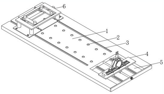
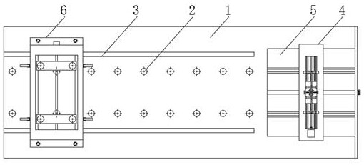
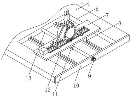
[0030] see Figure 1~6, the present invention proposes a technical solution, an auxiliary traction device for doctors in orthopedic departments, including a mounting base plate 1, a traction mounting groove 5 is opened on the right side of the top of the mounting base plate 1, and a traction body is arranged inside the traction mounting groove 5 4. The top of the installation base plate 1 is equidistantly provided with multiple groups of bracket concave holes 1, the traction main body 4 includes the traction movable plate 7, and the two sides of the traction movable plate 7 top are rotated with semi-arc parts 33, semi-arc The inner wall surface of the part 33 is bonded with an air bag 32, the air bag 32 is fixedly equipped with an air outlet 31, and the air inlet of the air bag 32 is fixedly installed with an air inlet 34, and the air inlet 34 is interspersed and installed in the On the semi-arc part 33, the outer wall of the semi-arc part 33 is welded with two shaft blocks-20...

Embodiment 2

[0036] see Figure 1~6 , on the basis of Embodiment 1, the present invention provides a technical solution: two dovetail chutes 3 are opened on the top of the installation base plate 1 and located on the left side of the traction installation groove 5, and the installation base plate 1 passes through the two dovetail chute 3. Sliding installation is provided with expanding main body 6, and expanding main body 6 comprises movable mounting plate 36, and the top of movable mounting plate 36 is provided with two bracket concave holes 2 37, and the both sides of movable mounting plate 36 tops are all installed with two An electric telescopic rod-39, fixedly connected with a top plate 40 between the movable ends of the four electric telescopic rods-39, the top of the top plate 40 runs through and is provided with a middle installation chamber 41, and the inner limit sliding of the middle installation chamber 41 is installed with two Movable installation bar 46, the both sides of mov...


PUM


Abstract

The auxiliary traction device comprises a mounting bottom plate, and a traction mounting groove is formed in the right side of the top of the mounting bottom plate. According to the auxiliary traction device for the orthopedics department doctor, when the legs of a patient are located between the two semi-arc-shaped pieces, due to the fact that an air bag is installed in the semi-arc-shaped pieces, inflation is conducted continuously through a manual inflation pump, air enters the air bag through an inflation pump connecting pipe and an air inlet in sequence, and the air bag is in an expanded state; the legs of a patient make full contact with the air bag, the clamping stability of the patient is improved, air in the air bag can be exhausted through the exhaust port, the legs of different sizes can be effectively and stably clamped through the two semi-arc-shaped pieces, the applicability is high, the air bag is made of soft materials, and the air bag is not prone to falling off. And secondary damage to the clamping part is avoided, the structure is more optimized, and the design is more reasonable.

Description

technical field [0001] The invention relates to the field of orthopedic auxiliary traction, in particular to an auxiliary traction device for doctors in orthopedic departments. Background technique [0002] In some orthopedic operations, it is necessary to use a traction device to assist the orthopedic operation. This application improves the prior art. The traction device in the prior art has the following deficiencies when it is in use. When positioning the patient's leg for traction, because it does not take protective measures for the leg, when When the legs are clamped and positioned, they cannot be effectively protected, and it is easy to cause secondary damage to the positioning of the legs during traction, and it is impossible to achieve effective protection for legs of different sizes. Its structure is not optimized enough, and its design is not reasonable enough. Contents of the invention [0003] The purpose of the present invention is to provide an auxiliary ...

Claims


Application Information

Patent Timeline
Patent Type & Authority Applications(China)
IPC IPC(8): A61G13/12A61B90/14A61B17/02A61B17/66
CPCA61G13/1245A61G13/125A61G13/1265A61G13/128A61B90/14A61B17/0206A61B17/66A61G2210/10
Inventor 崔冬马翔宇周大鹏于海龙元红项良碧
Owner GENERAL HOSPITAL OF THE NORTHERN WAR ZONE OF THE CHINESE PEOPLES LIBERATION ARMY
Learn More