Device for draining lymph fluid to veins

A technology of lymphatic fluid and equipment, applied in wound drainage device, suction device, drug device, etc., can solve problems such as disintegration of built-in battery

Pending Publication Date: 2022-05-13
新梵棨股份有限公司
View PDF0 Cites 0 Cited by
  • Summary
  • Abstract
  • Description
  • Claims
  • Application Information

AI Technical Summary

Problems solved by technology

[0006] The main purpose of the present invention is to propose a device for draining lymph to veins to reduce the number of surgeries or to solve the problems of possible disintegration of the built-in battery

Method used


Image

  • Device for draining lymph fluid to veins
  • Device for draining lymph fluid to veins
  • Device for draining lymph fluid to veins

Examples


Embodiment 1

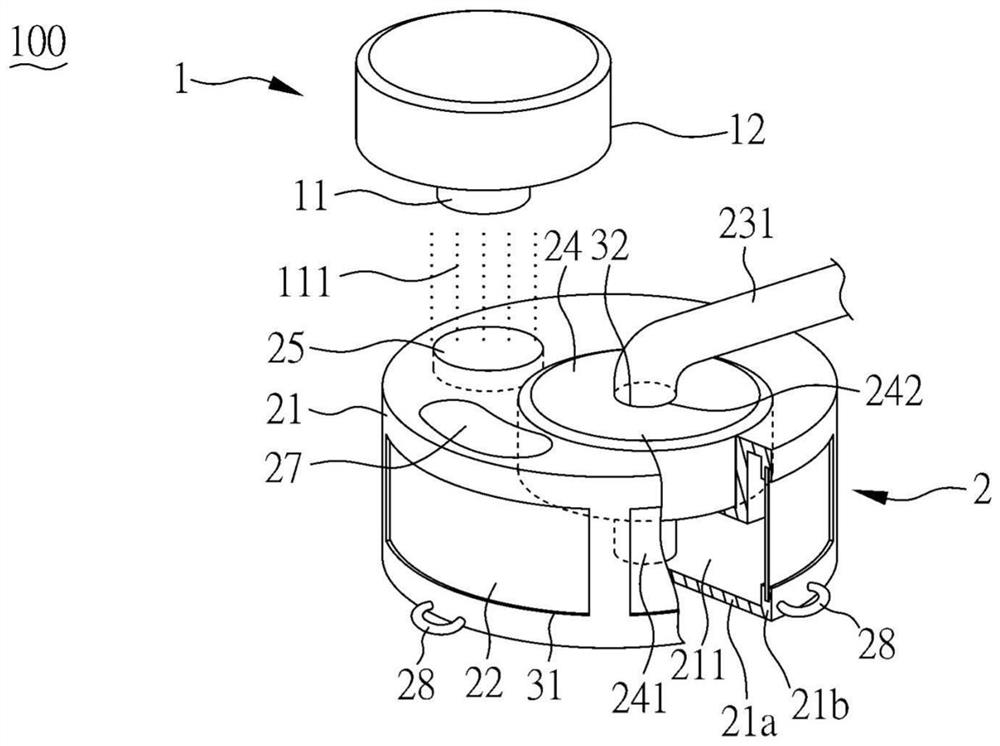
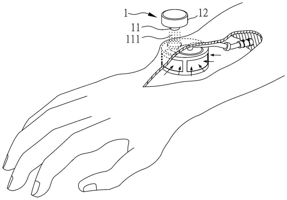
[0058] figure 1 A partial schematic view of the device 100 for draining lymph to veins according to Embodiment 1 of the present invention is shown. figure 2 A schematic diagram showing the implantation of the device 100 for draining lymph to veins according to Embodiment 1 of the present invention. image 3 A schematic diagram showing the device 100 for draining lymph to veins according to Embodiment 1 of the present invention.

[0059] Such as Figure 1 ~ Figure 3 As shown, the device 100 for draining lymph to veins in this embodiment includes a power supply device 1 and a drainage device 2, wherein the power supply device 1 includes a first sensing element 11 and a power supply element 12, and the power supply element 12 and the first sensing element 11 are electrically connected to each other. The connection is used to supply power to the first inductive element 11, and the first inductive element 11 is used to emit a radio wave 111, and is an induction coil, but not lim...

Embodiment 2

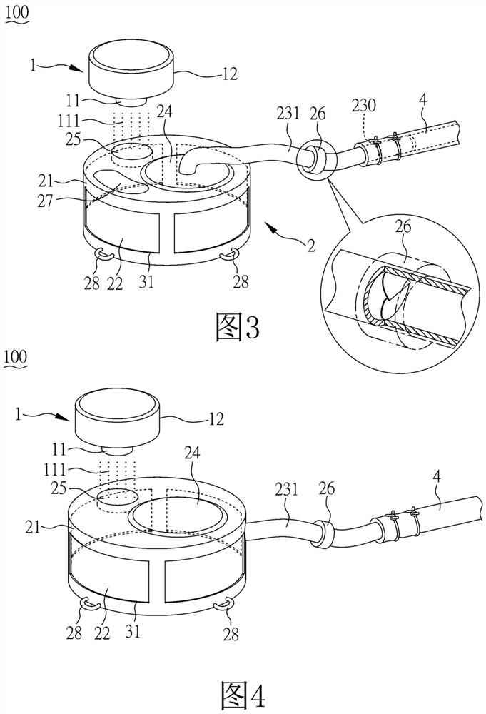
[0067] Figure 4 A schematic diagram showing the device 100 for draining lymph to veins according to Embodiment 2 of the present invention.

[0068] Such as Figure 4 As shown, the structure of this embodiment is similar to that of Embodiment 1, and has similar features and functions as Embodiment 1, so it will not be repeated here. The difference from Embodiment 1 is that the first conduit 231 is arranged in the receiving groove 21 side. In addition, the device 100 for draining lymph to veins in this embodiment does not have a drug injection silicone sheet 27 (such as image 3 shown). In addition, as long as it is reasonable, the details and features of each embodiment can also be matched and combined arbitrarily.

Embodiment 3

[0070] Figure 5 A schematic diagram of the device 100 for draining lymph fluid into veins according to Embodiment 3 of the present invention is shown.

[0071] Such as figure 1 and Figure 5 As shown, the structure of this embodiment is similar to that of Embodiment 1, and has similar features and functions as Embodiment 1, so it will not be repeated here, and the difference with Embodiment 1 is that it is not provided with a check valve 26 (such as image 3 shown) and the installation positions of the pump 24 and the second sensing element 25. In Embodiment 1, the pump 24 is arranged in the receiving tank 21, and the second sensing element 25 is also directly arranged in the receiving tank 21. However, in this embodiment, the pump 24 is arranged outside the receiving tank 21 and adjacent to the receiving tank 21. , is a micropump, but not limited thereto, the inlet port 241 of the pump 24 is connected to the second opening 32 on the tank wall 21a, and the outlet port 242 ...


PUM


Abstract

The invention provides equipment for draining lymph liquid to veins. The equipment comprises a drainage device. The drainage device comprises a containing groove, a permeable membrane, a first guide pipe, a second sensing element and a pump. The containing groove comprises a groove wall, a containing space is formed, and a first opening is formed in the groove wall. The permeable membrane is arranged at the first opening. One end of the first catheter is connected to the accommodation space, and the other end is connected to a vein. The second sensing element receives a radio wave emitted by a first sensing element of a power supply device so as to emit an electric signal. The pump is arranged in the containing groove and connected with the second sensing element, and the pump is driven to generate negative pressure in the containing space so as to guide the lymph to be drained to the vein through the first catheter.

Description

technical field [0001] The present invention relates to a lymphatic drainage device, in particular to a novel lymphatic drainage device suitable for effectively alleviating lymphedema. Background technique [0002] Lymphedema is the swelling that occurs when excess lymphatic fluid accumulates in body tissues. Normally, 10% of the arterial blood leaking from the capillaries, the protein-rich lymph fluid flows through the lymphatic vessels to the lymph nodes, and finally back to the veins. However, when the proximal lymph nodes are surgically removed, or even the function of the remaining lymph nodes is destroyed by radiation therapy, or the lymphatic system is naturally lost, or the lymphatic system is damaged by parasites, the lymph fluid will be difficult to recover and accumulate in the tissue. produce lymphedema. [0003] Generally, breast cancer patients are more prone to upper limb lymphedema. According to statistics, about 6-30% of breast cancer patients will develop...

Claims


Application Information

Patent Timeline
Patent Type & Authority Applications(China)
IPC IPC(8): A61M1/00A61M27/00
CPCA61M27/002A61M2205/82A61M2202/0405A61M1/80A61F2/2476A61M2205/8243A61M2205/8206A61M1/962A61M39/24A61M2205/04
Inventor 郑明辉
Owner 新梵棨股份有限公司
Why Eureka
Try Eureka