Energy-saving component

A technology of components and driving parts, applied in electrical components, mechanisms for generating mechanical power, electromechanical devices, etc., can solve problems such as small torque, motor environment restrictions, and difficulty in effectively improving efficiency

Pending Publication Date: 2022-06-07
李天德
View PDF0 Cites 0 Cited by
  • Summary
  • Abstract
  • Description
  • Claims
  • Application Information

AI Technical Summary

Problems solved by technology

[0004] However, in the conventional technology, due to the characteristics of the motor, the output torque is relatively small, and there are disadvantages such as heat generation, friction force, or power conversion loss during operation, so it is difficult to effectively improve the efficiency, and it is also impossible to convert all The input electric energy is completely converted into kinetic energy, thus limiting the environment in which the motor can be used

Method used


Image

  • Energy-saving component
  • Energy-saving component
  • Energy-saving component

Examples


Embodiment 1

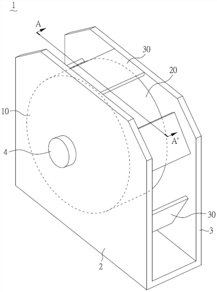
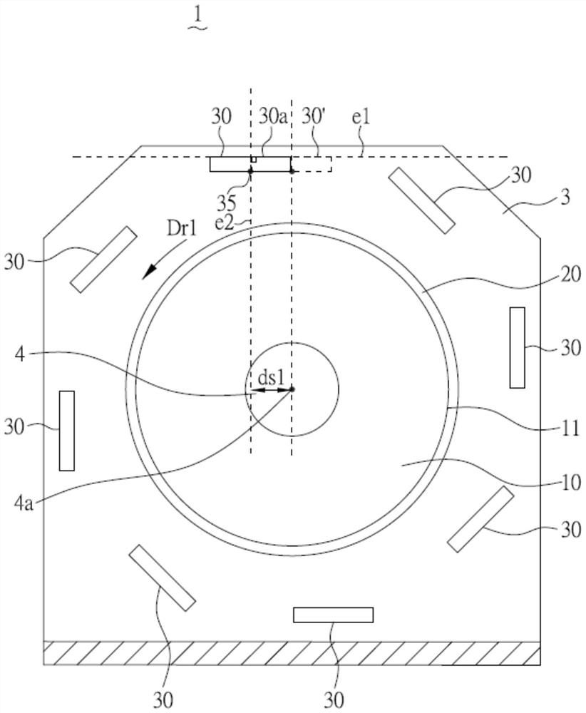
[0061] figure 1 A perspective view of the energy-saving member (1) of Example 1 of the present invention is shown. figure 2 The energy-saving member (1) of Example 1 of the present invention is shown along figure 1 A cross-sectional view of the A-A' line.

[0062] like figure 1 and figure 2 As shown, in the energy-saving component (1) for a power source of this embodiment, the energy-saving component (1) includes a first side plate (2), a second side plate (3), an axis (4a), an axis A part (4), an energy-saving runner (10), an outer surface (11), a permanent magnet (20) and a magnetic drive member (30). The energy-saving runner (10) is pivotally connected to the first side plate (2) and the second side plate (3) through the shaft portion (4), and has an outer surface (11), and the shaft portion (4) Connect the external rotating shaft (not shown in the figure), and drive the energy-saving runner (10) to rotate through the external rotating shaft (not shown in the figure)...

Embodiment 2

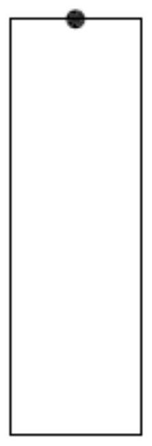
[0067] Fig. 4(A) shows a perspective view of the energy-saving member (1) of Example 2 of the present invention.

[0068] As shown in FIG. 4(A), the structure of this embodiment is similar to that of Embodiment 1, and has similar features and effects to Embodiment 1, so it will not be repeated here. The difference from Embodiment 1 is that this embodiment The permanent magnet (20) of the embodiment is a ring-shaped structure, and two permanent magnets (20) parallel to each other are arranged on the outer surface (11) of the energy-saving runner (10), but it is not limited to this; In an embodiment, a plurality of permanent magnets (20) parallel to each other can be arranged on the outer surface (11) of the energy saving wheel (10), as long as the outer surface (11) of the energy saving wheel (10) is sufficient to accommodate. In addition, as long as it is reasonable, the details and features of each embodiment can also be arbitrarily combined.

Embodiment 3

[0070] Fig. 4(B) shows a perspective view of the energy-saving member (1) of Example 3 of the present invention.

[0071] As shown in FIG. 4(B), the structure of this embodiment is similar to that of Embodiment 1, and has similar features and effects as Embodiment 1, so it will not be repeated here. The difference from Embodiment 1 is that this embodiment The permanent magnet (20) of the embodiment is composed of a plurality of micro-magnets arranged along a specific direction, and is also arranged on the outer surface (11) of the energy-saving runner (10), but is not limited thereto. In addition, as long as it is reasonable, the details and features of each embodiment can also be arbitrarily combined.


PUM


Abstract

The invention discloses an energy-saving component for a power source. The energy-saving component comprises an energy-saving rotating wheel, at least one permanent magnet and at least two magnetic driving pieces, the energy-saving rotating wheel is pivoted to a first side plate and a second side plate through an axis part and is provided with an outer surface, and the axis part is connected with an external rotating shaft and is driven by the external rotating shaft to rotate. The at least one permanent magnet is disposed on the outer surface. The at least two magnetic driving parts are correspondingly arranged corresponding to two opposite sides of the outer surface, and each magnetic driving part is arranged adjacent to the permanent magnet. Besides, when viewed from the section direction of one side of the energy-saving component, each magnetic driving piece is provided with a magnetic line starting point and a farthest edge far away from the energy-saving rotating wheel, and an extension line passing through the farthest edge is defined as a first extension line. An extension line of the shortest distance between the starting point of the magnetic force line and the first extension line is defined as a second extension line, and the second extension line does not pass through the axis of the axis part of the energy-saving rotating wheel.

Description

technical field [0001] The present invention relates to an energy-saving component for a power source, in particular to an energy-saving component for a motor. Background technique [0002] A motor is an electrical device that converts electrical energy into kinetic energy. In the world, nearly half of the electricity is consumed by the motor, and nearly 70% of the industrial electricity is used for the motor. It can be seen that the motor is closely related to daily life. Therefore, if the efficiency of the motor can be improved, it will help to save energy. [0003] The principle of conventional motors is that the inner coil is placed in a magnetic field, and when the inner coil is energized, the magnetic field generated around the rotor causes one side of the rotor to be pushed away and attracted to the other side of the rotor, thereby causing the rotor to start. When the rotor rotates 180 degrees, the current direction of the internal coil is reversed, and the magnetic ...

Claims


Application Information

Patent Timeline
IPC IPC(8): H02K53/00
CPCH02K53/00F03G7/00
Inventor 李天德
Owner 李天德
Why Eureka
Try Eureka