Automatic snow cleaning device for power equipment

A power equipment, automatic cleaning technology, applied in the substation/distribution device casing, heating device, lighting and heating equipment, etc., to achieve the effect of convenient retraction and improvement of cleaning efficiency and effect

Pending Publication Date: 2022-05-13
STATE GRID SHANDONG ELECTRIC POWER CO WUDI COUNTY POWER SUPPLY CO
View PDF0 Cites 0 Cited by
  • Summary
  • Abstract
  • Description
  • Claims
  • Application Information

AI Technical Summary

Problems solved by technology

[0005] (1) The technical problem to be solved by the present invention is: it is convenient for personnel to reduce the time for transporting snow removal equipment when cleaning snow on power equipment, and to clean the surface of the power cabinet by installing the snow removal device in advance in the power cabinet and manually controlling it lightly. Snow work saves time and effort, greatly improves cleaning efficiency and reduces equipment loss

Method used


Image

  • Automatic snow cleaning device for power equipment
  • Automatic snow cleaning device for power equipment
  • Automatic snow cleaning device for power equipment

Examples


Embodiment 1

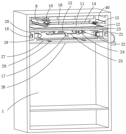
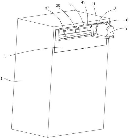
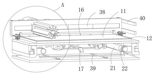
[0032] like figure 1 , figure 2 , image 3 , Figure 4 , Figure 5 , Image 6 , Figure 7 , Figure 8As shown, this embodiment proposes an automatic snow removal device for electric power equipment, including a power equipment cabinet 1, a sealing plate 26 is fixedly installed on the inside of the power equipment cabinet 1, a support plate 13 is movably installed on the inside of the power equipment cabinet 1, and the support plate One end of 13 is fixedly connected with a backboard 4, the upper surface of the backboard 4 is movably provided with a load-bearing plate 3, and one end of the load-bearing plate 3 is equipped with a snow clearing mechanism, which includes a swing opening 37 provided on the load-bearing plate 3, and The swinging block 41 slidingly installed with the load-bearing plate 3, the inside of the swinging block 41 is interspersed and rotated to install the rotating shaft 10, the outer surface of the rotating shaft 10 is provided with snow-clearing sh...

Embodiment 2

[0034] The scheme in embodiment 1 is further introduced below in combination with specific working methods, see the following description for details:

[0035] like figure 1 , Figure 4 , Figure 5 , Image 6 As shown, as a preferred embodiment, on the basis of the above method, further, the sliding mechanism includes a chute 19 fixedly installed on the two inner walls of the power equipment cabinet 1, and a sliding plate 20 slidably connected to the inner side of the chute 19. The adjacent sides of each slide plate 20 are all fixedly connected with the support plate 13, and the inner side of the chute 19 is fixedly connected with a stopper 18, and the slide plate 20 slides in the chute 19, so that the slide plate 20 drives the support plate 13 to move, and the stopper 18 Blocking it facilitates the installation and disassembly of the snow removal device and facilitates maintenance.

[0036] like figure 1 , Figure 4 , Figure 5 , Image 6 , Figure 8 As shown, as a p...

Embodiment 3

[0041] The schemes in Embodiment 1 and Embodiment 2 are further introduced below in conjunction with specific working methods, see the following description for details:

[0042] Specifically, when the automatic snow removal device for electric power equipment is working: the personnel first lifts the clamping plate 32, thereby driving the clamping rod 33 to lift and compress the spring 31, so that the clamping rod 33 is separated from the through hole 30, and then pushes up the push frame 27 so that Drive the cover block 22 to move to one end on the fixed rod 21, thereby driving the through rod 36 to pull the slide plate 20 to slide in the chute 19, so that the slide plate 20 drives the support plate 13 to move, thereby driving the load bearing plate 3 and the back plate 4 to move, so that the cleaning The snow mechanism, the drainage mechanism, the jacking mechanism, and the pushing mechanism move out of the power equipment cabinet 1 at the same time. After moving out, the pe...


PUM


Abstract

The invention relates to an automatic snow cleaning device for power equipment, and belongs to the field of snow cleaning of the power equipment, the automatic snow cleaning device comprises a power equipment cabinet, a sealing plate is fixedly mounted on the inner side of the power equipment cabinet, a supporting plate is movably mounted on the inner side of the power equipment cabinet, and one end of the supporting plate is fixedly connected with a back plate; a bearing plate is movably arranged on the upper surface of the back plate, a snow removing mechanism is installed at one end of the bearing plate and comprises a swing opening formed in the bearing plate and a swing block installed on the bearing plate in a sliding mode, a rotating shaft is rotatably installed in the swing block in a penetrating and penetrating mode, and snow removing pieces are annularly arranged on the outer surface of the rotating shaft at equal intervals; the snow cleaning device is simple in structure and convenient to use, time for transporting the snow cleaning device is shortened when a worker cleans snow on the power equipment, the snow cleaning device is installed in the power cabinet in advance, the snow cleaning work on the surface of the power cabinet is carried out through manual light operation, time and labor are saved, cleaning efficiency is greatly improved, and loss of the equipment is reduced.

Description

technical field [0001] The invention relates to an automatic snow removal device for electric power equipment, belonging to the field of snow removal devices for electric power equipment. Background technique [0002] Power equipment mainly includes two categories: power generation equipment and power supply equipment. Outdoor common power equipment includes power boxes and other equipment. Clean up, because some power equipment boxes are installed in mountainous areas or remote places to prevent long-term accumulation and penetration into the power box, so an automatic snow removal device is needed to assist in snow removal. [0003] At present, the existing snow removal devices for power equipment can only manually control a snow removal device to remove snow from the outside. Xue's efficiency is low, the workload is huge, and it is time-consuming and labor-intensive. [0004] Therefore we make improvement to this, propose a kind of electric equipment automatic snow clea...

Claims


Application Information

Patent Timeline
Patent Type & Authority Applications(China)
IPC IPC(8): B08B1/04B08B13/00F26B23/00H02B1/28H02B1/46H02B1/48
CPCB08B1/04B08B13/00F26B23/00H02B1/28H02B1/46H02B1/48
Inventor 张超鞠亚宁张金涛刘拥政徐刚郭建国陈杰杜洪燕程晓晗刘杰许斐徐成龙李新生王建伟付晓敏
Owner STATE GRID SHANDONG ELECTRIC POWER CO WUDI COUNTY POWER SUPPLY CO
Why Eureka
Try Eureka