

Friction stir welding device and friction stir welding method
A technology of friction stir and joining devices, applied in welding equipment, metal processing equipment, manufacturing tools, etc.
- Summary
- Abstract
- Description
- Claims
- Application Information
AI Technical Summary
Problems solved by technology
Method used
Image

Examples
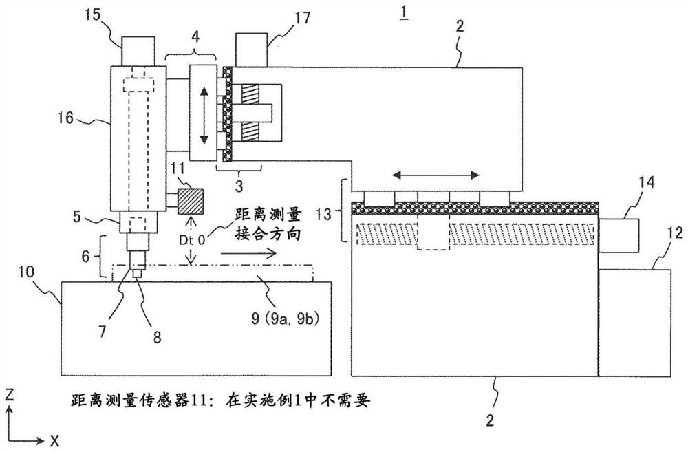
Embodiment 1
[0029] "Basic Controls of This Embodiment"
[0030] The friction stir welding device and the friction stir welding method of this embodiment control the Z-axis to move the driving mechanism up and down so that the current state quantity (current state quantity) during friction stir welding is smaller than the reference state quantity indicating the normal range of the state quantity , use the calculated absolute value of the correction to correct the position of the bonding tool in the vertical direction (downward direction of the Z axis), and when the current state quantity is greater than the reference state quantity, use the calculated absolute value of the correction The joint tool position is corrected in the vertical direction (Z-axis upward direction).
[0031] In this embodiment, friction stir welding in which the position of the joining tool is adjusted (corrected) using the load torque (load factor) of the spindle motor as the "state quantity" will be described.
[...
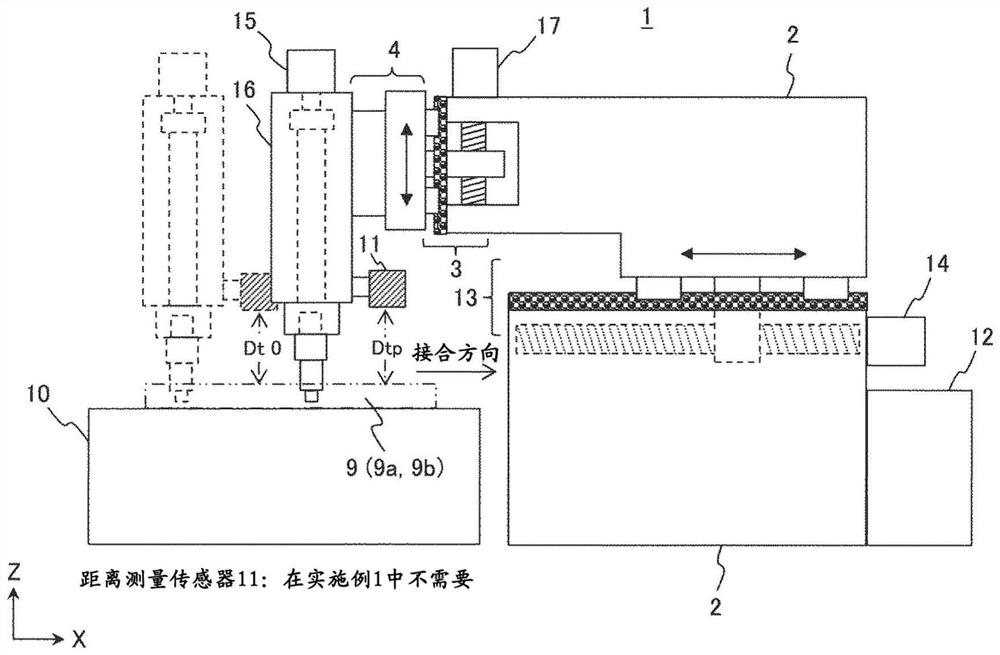
Embodiment 2
[0090] "Basic Controls of This Embodiment"
[0091] In the friction stir welding device and friction stir welding method of this embodiment, the Z-axis is controlled to move the drive mechanism up and down so that when the current state quantity in friction stir welding is smaller than the reference state quantity, the absolute value of the calculated correction amount is used. Correct the position of the bonding head in the upward direction of the Z axis (vertical upward direction), and correct the bonding head in the downward direction of the Z axis (vertical downward direction) by the absolute value of the calculated correction amount when the current state quantity is greater than the reference state quantity Location.
[0092] In this embodiment, friction stir welding in which the position of the bonding tool is controlled (corrected) using the distance from the surface of the member to be bonded to the predetermined position of the bonding head as the "state quantity" wi...
PUM
 Abstract
Description
Claims
Application Information