Power conversion device

A power conversion device and power conversion technology, applied in the direction of output power conversion device, high-efficiency power electronic conversion, AC power input conversion to DC power output, etc., can solve the problems of output current or torque adverse effects, and achieve high precision And it is easy to compensate, reduce the error, and expand the effect of the range

Active Publication Date: 2015-04-22
DAIKIN IND LTD
View PDF7 Cites 0 Cited by
  • Summary
  • Abstract
  • Description
  • Claims
  • Application Information

AI Technical Summary

Problems solved by technology

As a result, it will adversely affect the output current or torque

Method used


Image

  • Power conversion device
  • Power conversion device
  • Power conversion device

Examples


no. 1 approach

[0034] -Overall structure of the power conversion device-

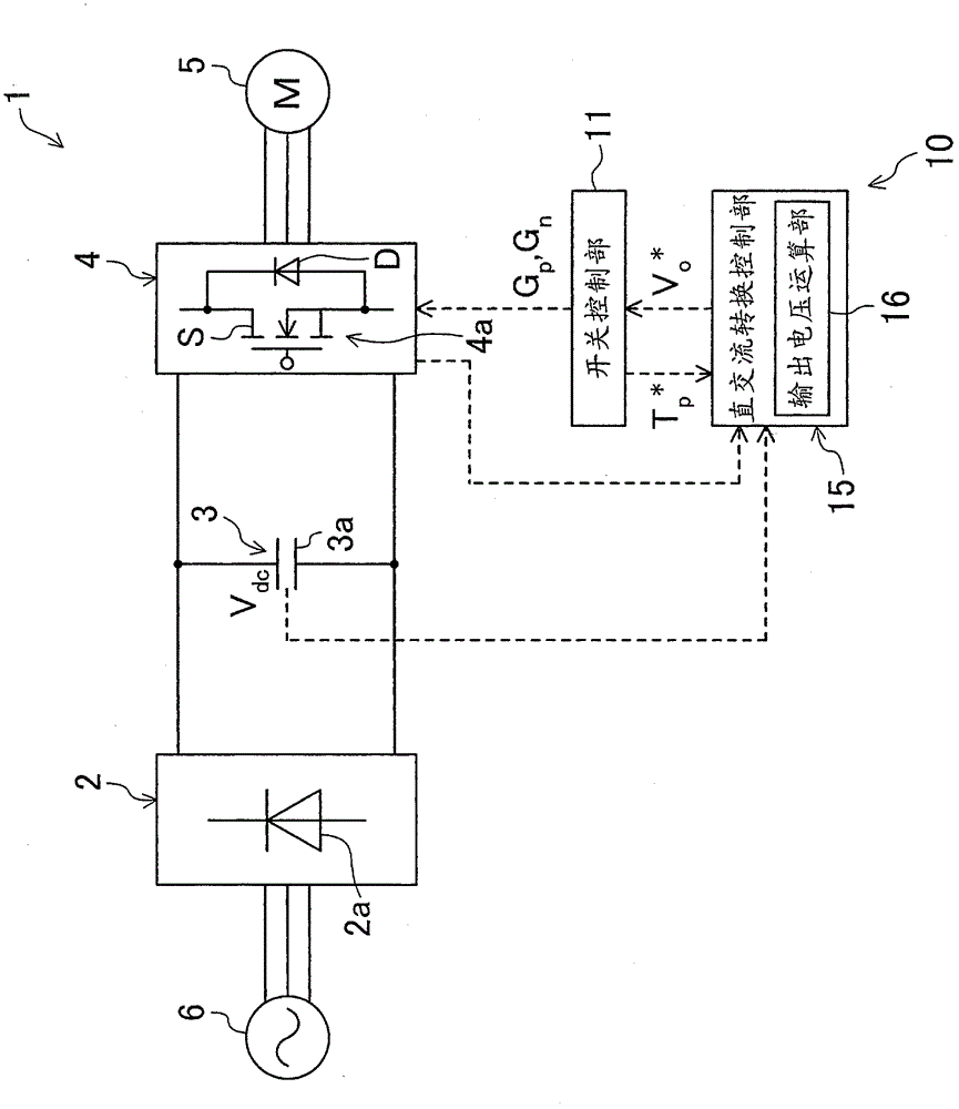
[0035] figure 1 The power conversion device 1 according to the first embodiment of the present invention is shown. The power conversion device 1 includes an AC-DC conversion circuit 2 , a capacitor circuit 3 and a DC-AC conversion circuit 4 . It should be noted that the above-mentioned power conversion device 1 is used, for example, to drive an electric motor 5 (hereinafter also referred to as a motor) of a compressor provided in a refrigerant circuit of an air conditioner. Here, although not shown in particular, the refrigerant circuit of the air conditioner is formed by connecting a compressor, a condenser, an expansion mechanism, and an evaporator into a closed circuit, and the refrigerant circulates in the refrigerant circuit to perform vapor compression refrigeration cycle. With this refrigerant circuit, the air cooled by the evaporator during cooling operation is supplied into the room, and the air heated by ...

other Embodiment approach

[0095] For the above-described embodiments, the following structures may also be employed.

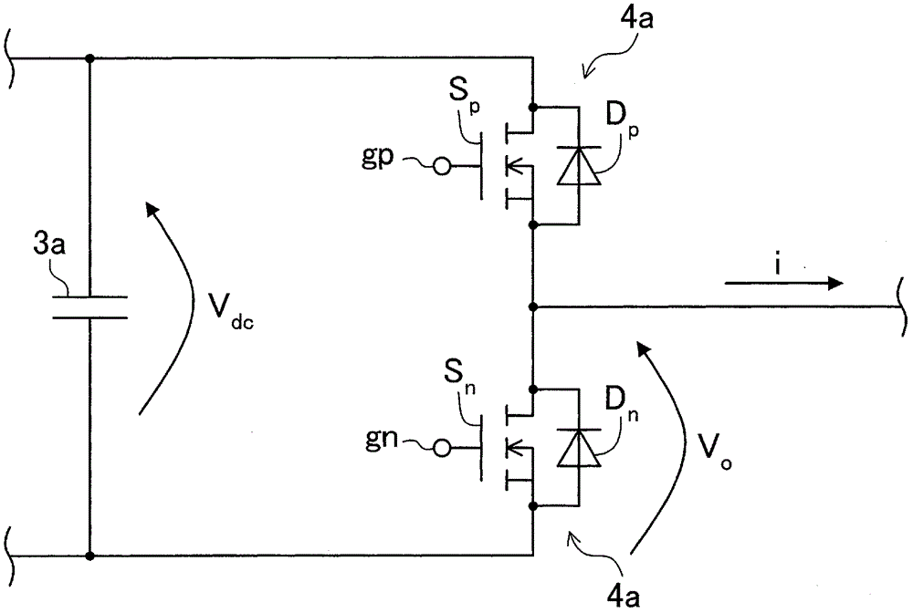
[0096] In each of the above-described embodiments, parasitic diodes formed in the chip constituting the switching elements Sp, Sn are used as the diodes Dp, Dn, but the present invention is not limited to this, and the switching elements Sp, Sn can also be configured by JFETs capable of reverse conduction Sn, so as to omit the diodes connected in antiparallel with the switching elements Sp and Sn. As a method of controlling the switch without such a diode, the switching element S is turned on at a predetermined timing when a reverse current flows through the switching element S. As shown in FIG.

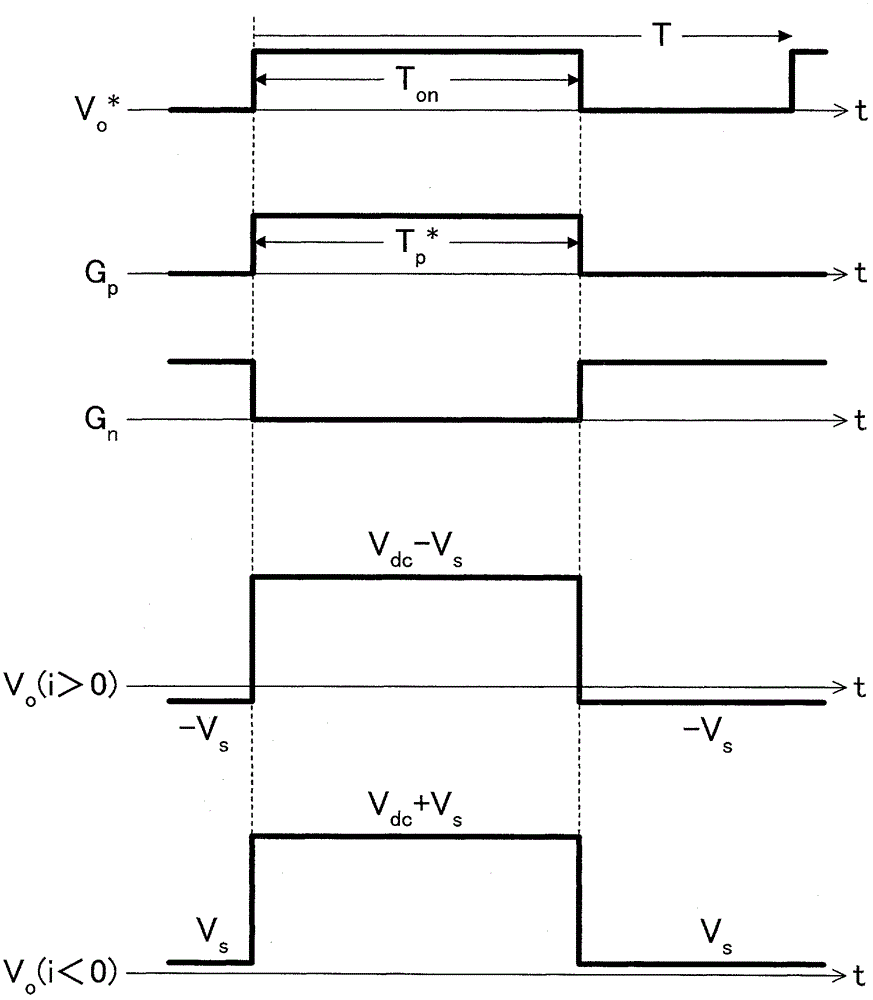
[0097] In the above-mentioned first embodiment, the output voltage command is taken into account by the DC-to-AC conversion control unit 15 for the on-state voltage drop of the switching elements Sp and Sn, but it is not limited to this, and the switch control unit 11 may determine the conduc...


PUM


Abstract

A power converter includes a power converter section (4) (e.g., an inverter circuit) having a plurality of switching elements (S p , S n ) in which a current can flow in a reverse direction, and a control section (10) which determines on-state time of each of the switching elements (S p , S n ) according to an output voltage of the power converter section (4), thereby switching on / off states of the switching elements (S p , S n ). The control section (10) instructs the power converter section (4) to perform synchronous rectification, and corrects the on-state time according to a drop of an on-state voltage of each of the switching elements (S p , S n ).

Description

technical field [0001] The present invention relates to a power conversion device including a power conversion unit having a plurality of switching elements. Background technique [0002] Conventionally, a power conversion device including a DC / AC conversion circuit having a plurality of switching elements and a switching control unit controlling the operation of the switching elements is widely known. Such a power conversion device is widely used, for example, in household appliances or industrial equipment that need to control the rotational speed or torque of a motor. [0003] Usually, in the power conversion device described above, a freewheel diode is connected in antiparallel to the switching element. Since the on-state voltage drops when current flows through these switching elements or freewheeling diodes, an error occurs in the actual output voltage with respect to the voltage command. As a result, output current or torque is adversely affected. [0004] In this ...

Claims


Application Information

Patent Timeline
Patent Type & Authority Patents(China)
IPC IPC(8): H02M1/38
CPCH02M2001/385Y02B70/1408H02M1/38H02M2007/2195H02M1/385H02M7/2195H02M7/48H02M7/5387Y02B70/10
Inventor 关本守满
Owner DAIKIN IND LTD
Why Eureka
Try Eureka