Image forming system, image reading apparatus, and image forming apparatus

一种图像读取装置、图像的技术,应用在测量装置、图像通信、仪器等方向,能够解决色标排列限制等问题

Active Publication Date: 2018-02-16
KONICA MINOLTA INC
View PDF11 Cites 0 Cited by
  • Summary
  • Abstract
  • Description
  • Claims
  • Application Information

AI Technical Summary

Problems solved by technology

Therefore, there are restrictions on the arrangement of color scales
Therefore, in the prior art described above, there is a limitation on the arrangement of color scales.

Method used


Image

  • Image forming system, image reading apparatus, and image forming apparatus
  • Image forming system, image reading apparatus, and image forming apparatus
  • Image forming system, image reading apparatus, and image forming apparatus

Examples


Embodiment approach 1

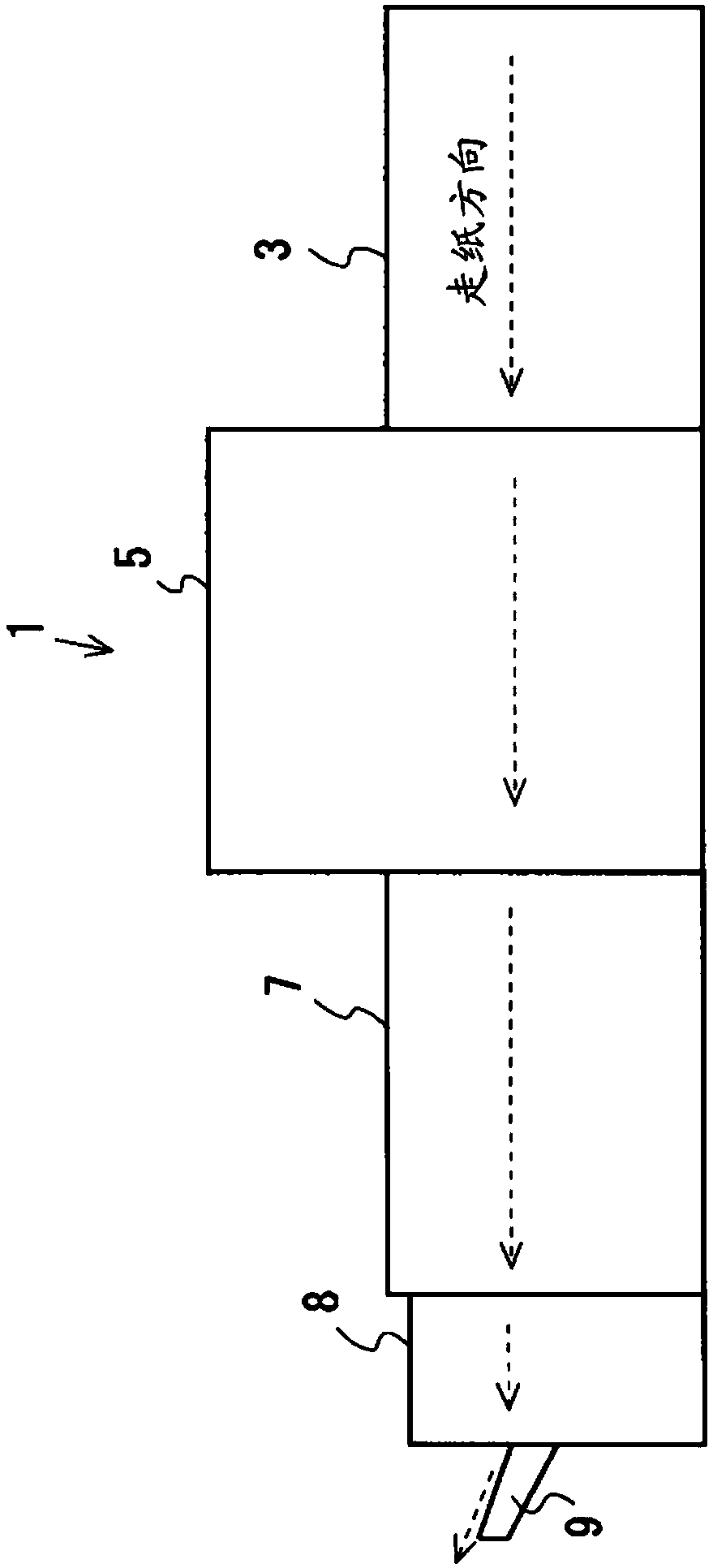
[0117] figure 1 It is a diagram showing an example of the overall configuration of the image forming system 1 according to Embodiment 1 of the present invention. Such as figure 1 As shown, the image forming system 1 has a paper feeding device 3 , an image forming device 5 , an image reading device 7 , and a paper discharge device 8 . The paper feeding device 3 supplies the paper medium P to the image forming device 5 . The image forming device 5 forms an image on the paper medium P supplied from the paper feeding device 3 . The image reading device 7 reads the paper medium P on which an image has been formed by the image forming device 5 and executes various processes. The paper discharge device 8 has a paper discharge tray 9 and discharges the paper medium P conveyed from the image reading device 7 to the paper discharge tray 9 .

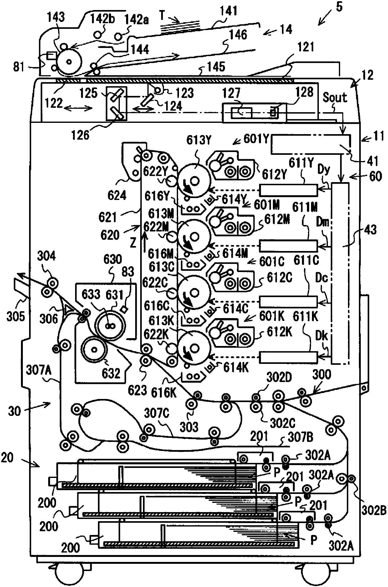
[0118] figure 2 It is a diagram showing a configuration example of the image forming apparatus 5 according to Embodiment 1 of the present in...

Embodiment approach 2

[0219] In Embodiment 2, the same reference numerals are assigned to the same configurations as in Embodiment 1, and description thereof will be omitted. In Embodiment 2, the temperature correction color patch is formed on the paper medium P along the FD direction.

[0220] Figure 10 It is a figure which shows an example of the temperature correction color patch formed on the paper medium P of Embodiment 2 of this invention. Such as Figure 10 As shown, temperature correction color patches are formed in the CD (16) column along the FD direction. In this case, the detection part 707 can detect the temperature of the temperature correction color patches respectively formed in CD(16) / FD(1)-CD(16) / FD(25). Therefore, since it is possible to detect a temperature change in the FD direction, it is possible to perform thermal discoloration correction with higher accuracy.

Embodiment approach 3

[0222] In Embodiment 3, the same components as those in Embodiments 1 and 2 are denoted by the same reference numerals, and description thereof will be omitted. In Embodiment 3, the temperature correction color patches are formed on the paper medium P in the CD direction, and the temperature correction color patches are formed on the paper medium P in the FD direction.

[0223] Figure 11 It is a figure which shows an example of the temperature correction color patch formed on the paper medium P concerning Embodiment 3 of this invention. Such as Figure 11 As shown, temperature correction color patches are formed in the FD(13) column along the CD direction. In addition, temperature correction color patches are formed in the CD (16) column in the FD direction. In this case, since the temperature difference along the CD direction and the temperature difference along the FD direction can be obtained, it is possible to estimate the temperatures of the temperature correction pat...


PUM


Abstract

An image forming system, an image reading apparatus, and an image forming apparatus are provided which can correct color values of images with low cost and high precision and improve the limitations for patch arrangement even in the state of influence of heat discoloration. A paper medium enables temperature correction patches with the same color to be formed at a reference position for detectingreference temperature and a comparison position different from the reference position. The image reading apparatus includes: a scanner that reads respective colors of the temperature correction patches and a colorimeter that performs colorimetry to the temperature correction patches; the image forming apparatus includes: a first calculator that calculates a color difference of color values of thetemperature correction patches at the reference position and at the comparison position; and a second calculator that calculates a temperature distribution; the temperature of the paper medium is distributed in such way that as a temperature difference between a first position and a second position increases, the color difference increases.

Description

technical field [0001] The present invention relates to an image forming system, an image reading device and an image forming device. Background technique [0002] Conventionally, it is known that the colorimetric measurement of a color patch formed on a paper medium is affected by a thermal discoloration phenomenon. The thermal discoloration phenomenon means that the colored object forming the color of the color mark changes according to the temperature, so that the color of the color mark changes. Therefore, when performing colorimetric measurement on a color patch formed on a paper medium, an error due to temperature may be included in the colorimetric measurement result due to the temperature of the paper medium. [0003] Therefore, it is proposed to measure the chromaticity based on the chromaticity measurement value of the color scale and the temperature when the chromaticity measurement is performed on the color scale by referring to a chart that associates the refer...

Claims


Application Information

Patent Timeline
Patent Type & Authority Applications(China)
IPC IPC(8): H04N1/00H04N1/60
CPCH04N1/00814H04N1/6033G01K11/12H04N1/6044H04N2201/0094
Inventor 林健一山田洋平井口幸宣佐佐木智
Owner KONICA MINOLTA INC
Why Eureka
Try Eureka