X-ray fluoroscopy device and afterimage correction method for X-ray fluoroscopy images

A technology of fluoroscopy and X-rays, which is applied in the fields of radiological diagnostic equipment, medical science, and diagnosis, and can solve the problems of diagnostic impact and large X-ray exposure dose, etc.

Active Publication Date: 2019-05-10
HITACHI HEALTHCARE MFG LTD
View PDF1 Cites 0 Cited by
  • Summary
  • Abstract
  • Description
  • Claims
  • Application Information

AI Technical Summary

Problems solved by technology

In "photography", the X-ray exposure dose is larger than that in "fluoroscopy", so electrical signals remain in the X-ray detector, and this electrical signal appears as an afterimage in the image obtained by fluoroscopy after photography, which is sometimes useful for diagnosis have an impact

Method used


Image

  • X-ray fluoroscopy device and afterimage correction method for X-ray fluoroscopy images
  • X-ray fluoroscopy device and afterimage correction method for X-ray fluoroscopy images
  • X-ray fluoroscopy device and afterimage correction method for X-ray fluoroscopy images

Examples


Embodiment approach 1

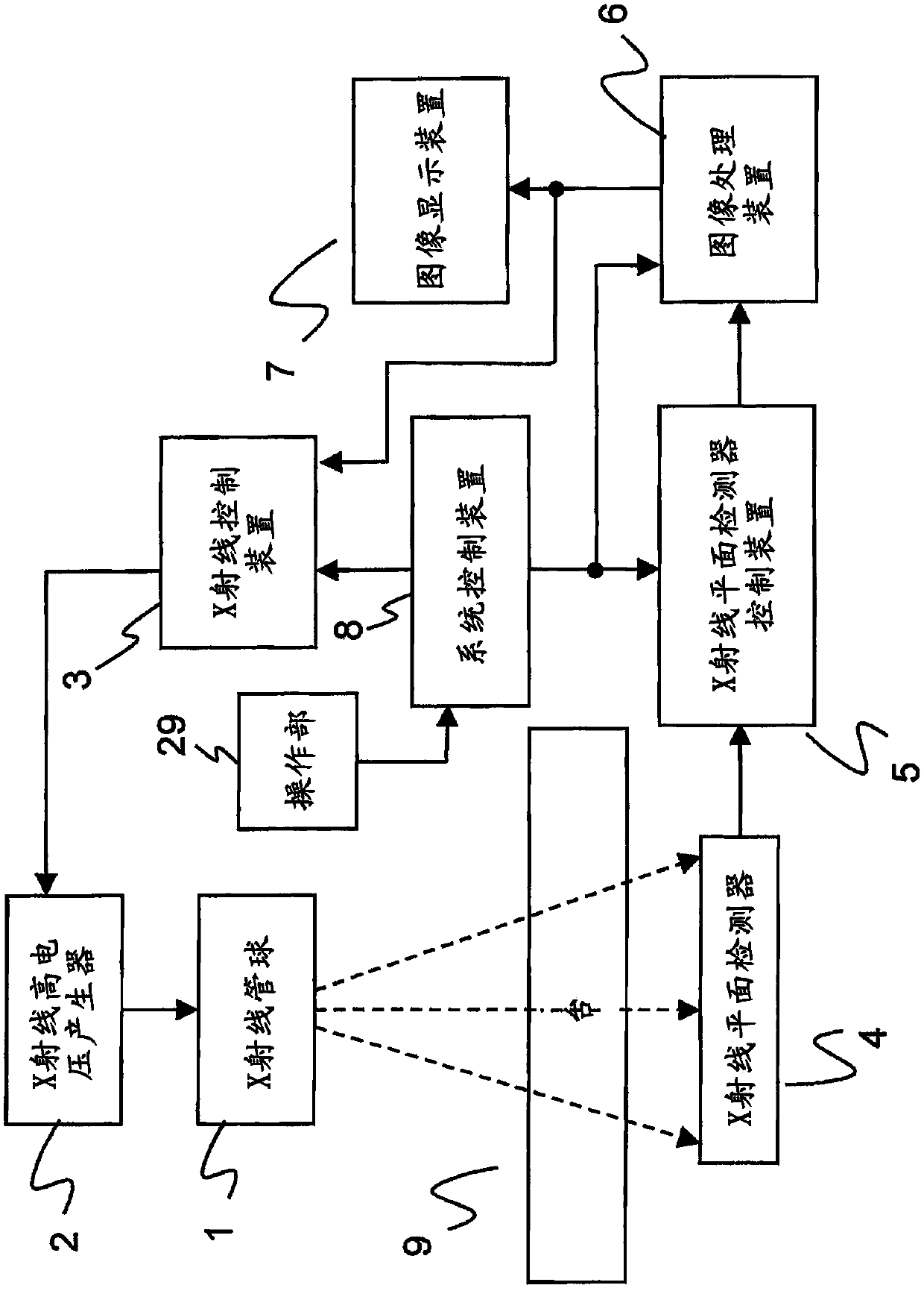
[0032] figure 1 It is a diagram showing the overall configuration of the X-ray fluoroscopy apparatus according to the first embodiment.

[0033] Such as figure 1 In this way, the X-ray fluoroscopy device has: an X-ray tube 1, which irradiates X-rays; an X-ray high-voltage generator 2, which is used to supply power (tube voltage / tube current) to the X-ray tube 1; Device 3, which controls the X-ray high voltage generator 2; X-ray plane detector 4, which is arranged opposite to the X-ray tube 1; platform 9, which is arranged between the X-ray tube 1 and the X-ray plane detector Between 4; operating part 29; X-ray plane detector control device 5; image processing device 6; image display device 7; system control device 8. The object to be tested is mounted on the stage 9 . The X-ray plane detector 4 detects X-rays irradiated from the X-ray tube 1 and transmitted through the subject mounted on the stage 9 .

[0034] The X-ray plane detector control device 5 reads the image detec...

Embodiment approach 2

[0067] Next, use Figure 7 , Figure 8 An X-ray fluoroscopy apparatus according to Embodiment 2 will be described.

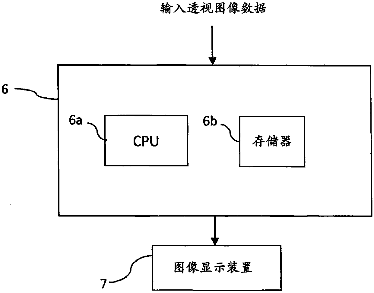
[0068] In Embodiment 1, there is a structure in which the memory 6b has a Mask for storing the latest n afterimage images. 1 [x, y] ~ Mask n [x, y] area, in Figure 4 In the step 34, calculate afterimage image Mask each time n When [x, y], it is stored in the memory 6b, and the afterimage image is updated. In addition, in step 35, compare n afterimage images Mask for each pixel 1 [x, y] ~ Mask n [x, y] pixel value, select the maximum value Mask max [x,y].

[0069] In Embodiment 2, there is a structure in which only one afterimage image Mask is stored in the memory 6b. max [x, y] area, in Figure 7 In step 134 of , calculate afterimage image Mask each time n [x, y], in step 135, compare the afterimage image Mask in the memory 6b max [x, y] and the corresponding pixel value of each pixel, select a large pixel value, and update the afterimage image Mask...

Embodiment approach 3

[0082] then use Figure 9 , Figure 10 Embodiment 3 will be described.

[0083] In Embodiment 2, it has the following structure, that is, if in Figure 7 Calculate afterimage image Mask in step 134 of n [x, y], then compare the afterimage image Mask in the memory 6b in step 135 max [x, y] and Mask n The pixel value of each pixel corresponding to [x, y], select a large pixel value as the afterimage image Mask max The pixel value of [x, y] is stored in the memory 6b, but in Embodiment 3, in Mask max When [x, y] is an afterimage signal generated in the past shooting, it is configured as follows in consideration of attenuation in the n-time shooting.

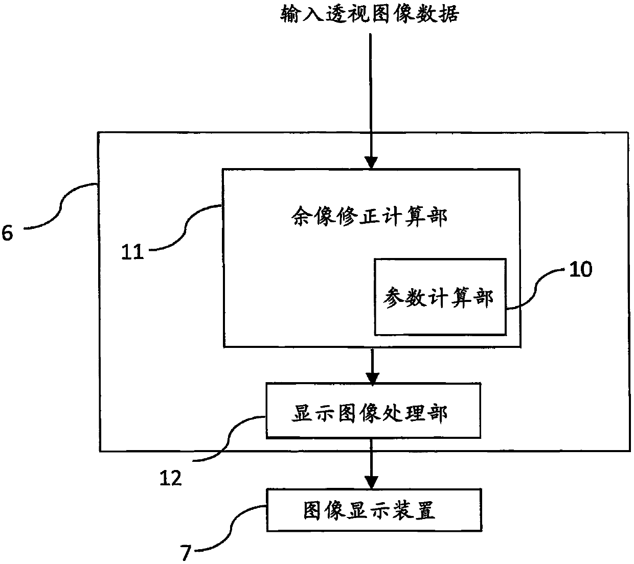
[0084] That is, the afterimage correction calculation unit 11 compares the pixel value of the afterimage image obtained after the current shooting with the pixel value of the afterimage image generated in the previous shooting before the current shooting, and the difference is the The pixel value of the afterimage image obtai...


PUM


Abstract

Provided is an X-ray fluorography apparatus and an afterimage correction method for X-ray fluoroscopic image, which can correct the afterimage component with high accuracy even when photographing and perspective are alternately repeated. Each time an X-ray photographic image is obtained, a photographed afterimage image is obtained for each pixel corresponding to the afterimage image obtained after the current image acquisition and the afterimage image obtained after the previous image acquisition. The value of the decay of a pixel value of an image is obtained from a function of time. Then, the pixel value of the perspective image obtained after this photographing is subtracted from the calculated attenuation value, thereby removing the afterimage.

Description

technical field [0001] The invention relates to an X-ray perspective photography device with afterimage correction function. Background technique [0002] Generally, the X-ray fluoroscopy system alternately performs "photography" in which X-rays are irradiated to obtain and display images, and "fluoroscopy" in which continuous images are obtained while continuously irradiating X-rays and a moving image is displayed. In "photography", the X-ray exposure dose is larger than that in "fluoroscopy", so electrical signals remain in the X-ray detector, and this electrical signal appears as an afterimage in the image obtained by fluoroscopy after photography, which is sometimes useful for diagnosis make an impact. [0003] Therefore, in the technique described in Patent Document 1, an afterimage image is obtained by acquiring an image without irradiating X-rays immediately after imaging. Then, using the attenuation characteristic of the afterimage component obtained in advance and...

Claims


Application Information

Patent Timeline
Patent Type & Authority Patents(China)
IPC IPC(8): A61B6/00
CPCA61B6/00A61B6/5235
Inventor 藤川真里天明宏之助万木贵宏中村正
Owner HITACHI HEALTHCARE MFG LTD
Why Eureka
Try Eureka