Chip welding line defect detection method and device

A defect detection and welding line technology, applied in the field of defect detection, can solve problems such as difficult detection

Pending Publication Date: 2022-05-13
GUANGDONG UNIV OF TECH
View PDF0 Cites 0 Cited by
  • Summary
  • Abstract
  • Description
  • Claims
  • Application Information

AI Technical Summary

Problems solved by technology

[0003] In today's market, the method of detecting the chip welding line of the circuit board is usually manual inspection by experienced employees. This inspection process is very dependent on the experience level of the employees. In addition, due to the size of the chip and other reasons, manual inspection is very difficult.

Method used


Image

  • Chip welding line defect detection method and device
  • Chip welding line defect detection method and device
  • Chip welding line defect detection method and device

Examples


Embodiment Construction

[0041] The idea, specific structure and technical effects of the present invention will be clearly and completely described below in conjunction with the embodiments and accompanying drawings, so as to fully understand the purpose, scheme and effect of the present invention. It should be noted that, in the case of no conflict, the embodiments in the present application and the features in the embodiments can be combined with each other. The same reference numbers are used throughout the drawings to indicate the same or similar parts.

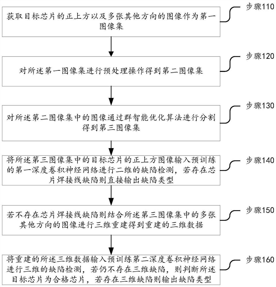
[0042] refer to figure 1 , embodiment 1, the present invention proposes a kind of chip welding line defect detection method, comprises the following:

[0043] Step 110, acquiring images directly above the target chip and multiple images in other directions as the first image set;

[0044] Step 120, performing a preprocessing operation on the first image set to obtain a second image set;

[0045] Step 130, segmenting the images in the second i...


PUM


Abstract

The invention relates to a chip welding line defect detection method. The method comprises the following steps: acquiring a plurality of images right above a target chip and in other directions as a first image set; performing preprocessing operation on the first image set to obtain a second image set; segmenting the images in the second image set through a swarm intelligence optimization algorithm to obtain a third image set; inputting an image right above the target chip in the third image set into a pre-trained first deep convolutional neural network for two-dimensional defect detection, and directly outputting a defect type if a chip welding line defect exists; if the chip welding line defect does not exist, performing three-dimensional reconstruction by combining the plurality of images in other directions in the third image set to obtain reconstructed three-dimensional data; and inputting the reconstructed three-dimensional data into a pre-trained second deep convolutional neural network for three-dimensional defect detection. Through the two-dimensional and three-dimensional fusion detection method, the defect that two-dimensional information is not comprehensive is overcome, and the defects that only the three-dimensional detection technology is large in calculation amount and low in speed are overcome.

Description

technical field [0001] The invention relates to the technical field of defect detection, in particular to a method and device for detecting a chip bonding line defect. Background technique [0002] When the circuit board is completed, it is often necessary to inspect its chip bonding line to control its defects. [0003] In today's market, the method of detecting the chip bonding line of the circuit board is usually manual inspection by experienced employees. This inspection process is very dependent on the experience level of the employees. In addition, due to the size of the chip and other reasons, manual inspection is very difficult. . Contents of the invention [0004] The purpose of the present invention is to provide at least one of the deficiencies of the prior art and provide a method and device for detecting a chip bonding line defect. [0005] In order to achieve the above object, the present invention adopts the following technical solutions: [0006] Specifi...

Claims


Application Information

Patent Timeline
Patent Type & Authority Applications(China)
IPC IPC(8): G06T7/00G06T7/11G06T7/136G06T7/55G06V10/44G06V10/764G06V10/82G06K9/62G06N3/04G06N3/08
CPCG06T7/0004G06T7/11G06T7/136G06T7/55G06N3/08G06T2207/10004G06T2207/20081G06T2207/20084G06T2207/30141G06N3/048G06N3/045G06F18/241
Inventor 陈玉冰陈新度吴磊
Owner GUANGDONG UNIV OF TECH
Why Eureka
Try Eureka