Optimized finite control set model prediction method for NPC three-level rectifier

A limited control set, three-level rectification technology, applied in the fields of power electronics and power transmission, can solve the problems of difficult weight coefficient design, unstable switching frequency, high switching frequency, achieve good dynamic and steady performance, and relieve calculation pressure , the effect of reducing the switching frequency

Pending Publication Date: 2022-05-13
CHINA UNIV OF MINING & TECH
View PDF0 Cites 3 Cited by
  • Summary
  • Abstract
  • Description
  • Claims
  • Application Information

AI Technical Summary

Benefits of technology

The technical effect described this patented technology helps reduce power consumption while maintaining high-speed processing capabilities for data transmission systems. By adjusting specific parameters such as timing or voltage levels based on an expected value called target deviations (TDOs), it can improve efficiency without increasing computational complexity. This results in faster operation times due to less calculations needed but still achieving stable operating conditions over longer periods.

Problems solved by technology

This patented technical problem addressed by this patents relates to improving the performance of power converters that use pulse width modulation (PWM) techniques like triac or FSMAC systems due to their ability to achieve net zero voltages at both ends without generating excessively distorted electrical signals during operation. Current methods have limitations including complicated circuitry designs requiring heavy weights and calculations time consuming.

Method used


Image

  • Optimized finite control set model prediction method for NPC three-level rectifier
  • Optimized finite control set model prediction method for NPC three-level rectifier
  • Optimized finite control set model prediction method for NPC three-level rectifier

Examples


Embodiment Construction

[0021] An NPC three-level rectifier optimization finite control set model prediction method proposed by the present invention will be further described in detail below in conjunction with the accompanying drawings and specific implementation steps.

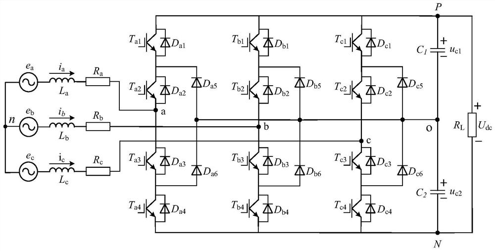
[0022] An NPC three-level rectifier optimization finite control set model prediction method, figure 1 Give the circuit topology diagram of NPC three-level rectifier. As shown in the figure, the NPC topology is divided into three bridge arms, each bridge arm is composed of 4 switching devices, 4 freewheeling diodes and 2 clamping diodes, and two capacitors C are connected in parallel on the DC side 1 and C 2 , L and R are grid side filter inductance and equivalent resistance respectively.

[0023] Firstly, the discrete mathematical model of the three-level PWM rectifier is established, assuming that the power device is an ideal switching device, and its conduction voltage drop and dead zone delay are ignored. By controlling the ...


PUM


Abstract

The invention discloses an NPC three-level rectifier optimization finite control set model prediction method, and relates to the field of power electronics and power transmission. According to the method, firstly, a three-level PWM rectifier discrete prediction model is established and initialized, state sampling is carried out on a PWM rectification system, then a predicted value and an expected value of a system state are calculated according to a recorded optimal switching vector, finally, whether a current error and a neutral-point potential error meet reference deviation at the same time or not is judged, and finally, whether the current error and the neutral-point potential error meet reference deviation or not is judged. If yes, recording the switching vector at the previous moment, and outputting the switching state; if not, the reference voltage is calculated, the sector where the reference voltage is located is judged, the value function of the switching state of the sector is solved, the switching vector with the minimum value function is recorded, and the switching state of the switching vector is output. The method has the advantages that when the current error and the neutral-point potential error are controlled within a certain range, the average switching frequency of the converter can be reduced, when the current error and the neutral-point potential error exceed the range, 27 times of traversal are reduced to 10 times, the calculation burden is reduced, and the method is suitable for being applied to a high-power PWM rectifier.

Description


Claims


Application Information

Patent Timeline
Owner CHINA UNIV OF MINING & TECH
Why Eureka
Try Eureka