
Dry ice generating and cleaning device

A cleaning device, dry ice technology, applied in cleaning methods and utensils, cleaning methods using liquids, carbon compounds, etc., can solve the problems of low use efficiency of dry ice pellets, melting of dry ice pellets, etc., to prevent secondary cleaning of objects to be cleaned, Easy to store, uniform size effect

Inactive Publication Date: 2022-05-13
金好珍
View PDF10 Cites 0 Cited by
  • Summary
  • Abstract
  • Description
  • Claims
  • Application Information

AI Technical Summary

Problems solved by technology

[0008] However, in the above-mentioned Patent Document 1, the dry ice blasting device is configured to drop the dry ice pellets produced outside into the hopper, and crush and spray the dropped dry ice pellets to the object to be cleaned. The phenomenon that part of the dry ice pellets melts in the weather, which has the problem of low efficiency of dry ice pellets

Method used


Image

  • Dry ice generating and cleaning device
  • Dry ice generating and cleaning device
  • Dry ice generating and cleaning device

Examples


Embodiment Construction

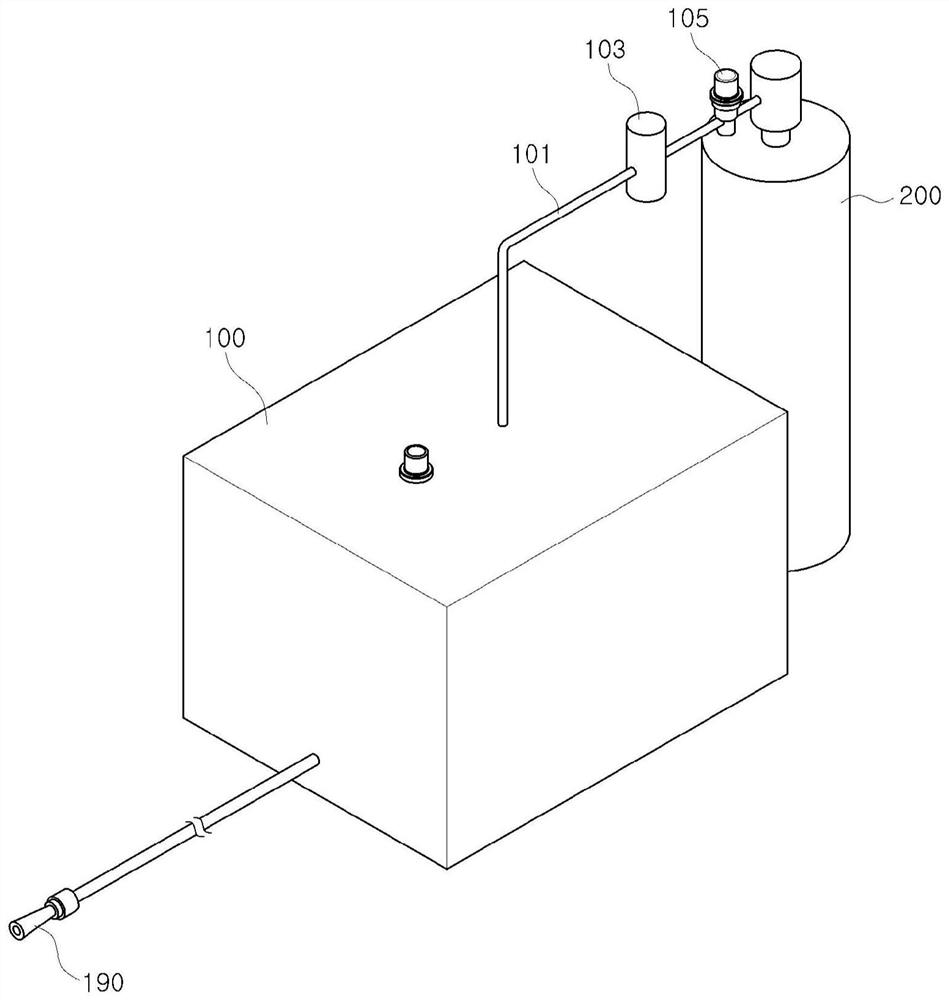
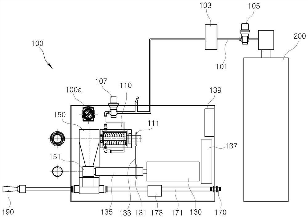
[0043] Such as figure 1 , figure 2 As shown, the dry ice generation and cleaning device according to an embodiment of the present invention includes a supply tank 200 containing liquefied carbon dioxide and a chamber 100 for generating dry ice and cleaning it.

[0044] The chamber 100 is equipped with a housing space in which a structure for generating and ejecting dry ice can be installed, and can be equipped with a switch 100a for controlling the generation and ejection of dry ice on the outside.

[0045] Also, the chamber 100 may be protrudingly provided with a nozzle 190 on the outside so that dry ice can be ejected.

[0046] The supply tank 200 is provided with a connection pipe 101 between the chamber 100 and the supply tank 200 in order to supply liquefied carbon dioxide to the chamber 100 , and a first regulator 103 , a second regulator 107 and a connection valve 105 may be provided in the connection pipe.

[0047] The first regulator 103 is provided near the supply...


PUM


Abstract

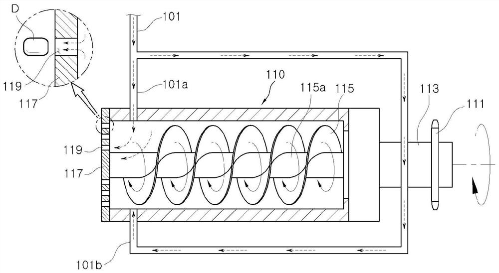
According to one embodiment of the present invention, a dry ice generating and cleaning apparatus comprises: a supply tank containing liquefied carbon dioxide; a connection pipe connected to the supply tank and the interior of the chamber; a generation filter which is connected to the connection pipe, receives the liquefied carbon dioxide from the supply tank, and generates dry ice crystals from the liquefied carbon dioxide; a hopper for accommodating the dry ice crystals generated by the generation filter; a drive motor that supplies power to the generation filter; and a nozzle for spraying the dry ice crystals accommodated in the hopper.

Description

technical field [0001] The invention relates to a dry ice generating and cleaning device. More specifically, it relates to a dry ice generating and cleaning device for simultaneously performing a dry ice generating process and a cleaning process inside a chamber. Background technique [0002] Usually, in the production process of parts, various foreign substances adhere to the surface of the produced parts, and a separate cleaning process for removing these foreign substances is passed through. [0003] According to this cleaning process, an operator manually performs cleaning operations such as shot blasting, steam cleaning, and solvent treatment on the produced parts, or cleaning operations using brushes or the like to remove foreign matter adhering to the surface. [0004] However, the above-mentioned cleaning process is manually performed by an operator, and there is a disadvantage that the quality of the cleaning operation varies depending on the operator's proficiency...

Claims


Application Information

Patent Timeline
Patent Type & Authority Applications(China)
IPC IPC(8): C01B32/55B08B3/02
CPCC01B32/55B08B3/02B08B7/0092B08B3/10F17C3/00
Inventor 金好珍
Owner 金好珍
Learn More