

Coupling
A coupling and bearing technology, applied in couplings, elastic couplings, mechanical equipment, etc., can solve the problems of low efficiency, stress, system imbalance, etc., and achieve the effect of reducing friction and wear
- Summary
- Abstract
- Description
- Claims
- Application Information
AI Technical Summary
Problems solved by technology
Method used
Image

Examples
Embodiment Construction
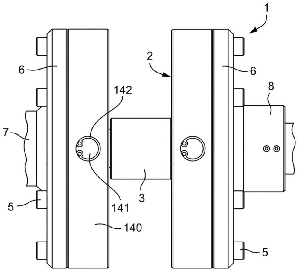
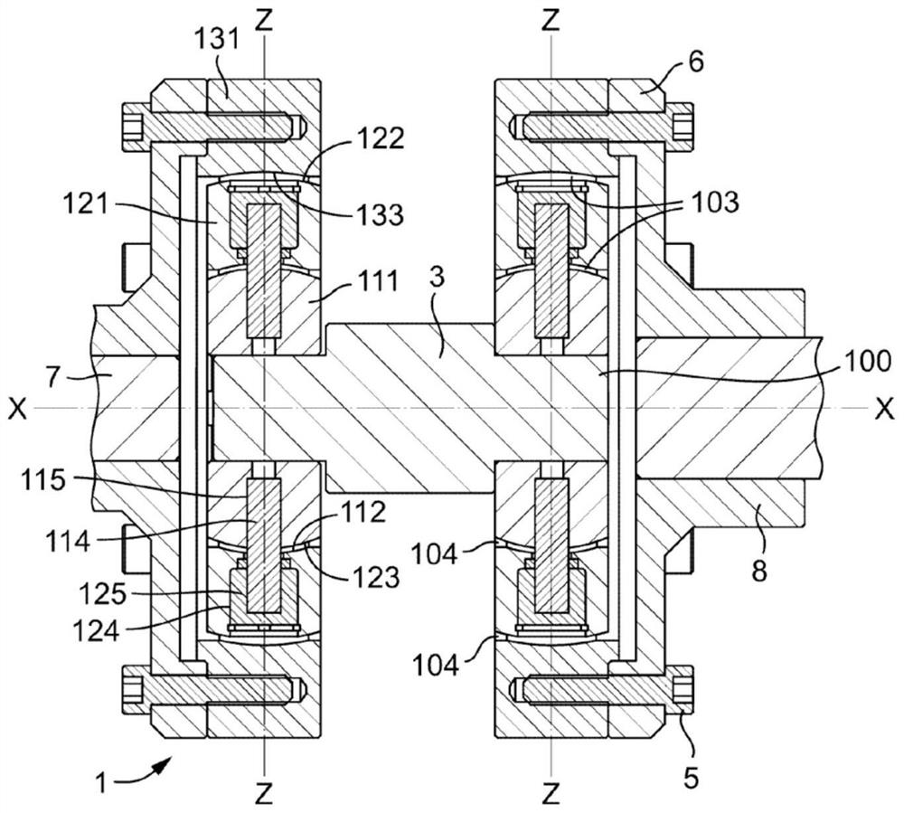
[0032] Figure 1 to Figure 4 Two example couplings 1 and 2 of the invention are shown joined by a shaft 3 used as a replacement for a Carden shaft.
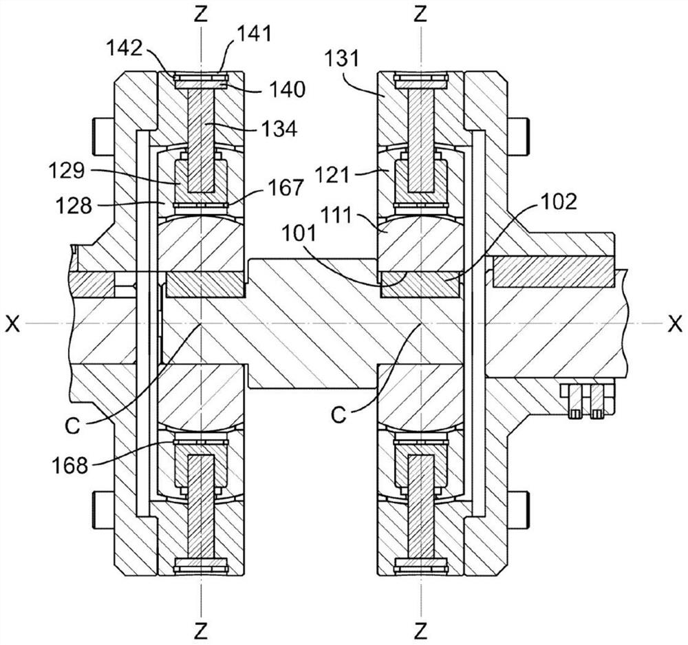
[0033] Each of the couplings 1 and 2 includes an inner ring member 111 , a middle ring member 121 and an outer ring member 131 . The center of the inner member 111 is located on the central axis X. As shown in FIG. The inner member 111 has an outer convex spherical surface 112 , which is a convex spherical surface centered at point C on the central axis X .
[0034] The inner annular member 111 has a central aperture 100 to receive the shaft 3 . The central aperture 100 has a keyway 101 which is engaged by a corresponding key 102 on the shaft 3 . Alternatively, the ends of the shaft member 3 may have splines to engage corresponding splines around the central aperture.
[0035] The intermediate annular member 121 has an inner concave spherical surface 123 which is a spherical segment complementary to the outer convex spherical...
PUM
 Abstract
Description
Claims
Application Information