
Multi-ring file hole clamp

A technology of hole clips and files, which is applied in binding, printing, etc., can solve the problems of large switch structure, inability to fold backwards, and damaged inner pages of paper holes, etc. The effect of tearing

Pending Publication Date: 2022-05-17
张 智源
View PDF0 Cites 0 Cited by
  • Summary
  • Abstract
  • Description
  • Claims
  • Application Information

AI Technical Summary

Problems solved by technology

The former closed coil (such as spiral ring binder) has the characteristics of flexible operation and can be folded in half at 360 degrees, which is convenient for one-handed operation and requires less space. However, because the coil is in a closed state after the finished product is completed, it cannot be opened. , so it is impossible to arbitrarily add or replace paper
The latter can open and close the half-ring (such as the loose-leaf ring binder) because the half-ring can be opened and closed, so the user can change its inner pages at will, but because of the switch structure The volume is usually relatively large, so it lacks the flexible operation characteristics of the closed coil, cannot be folded backwards, and it is difficult to hold it with one hand when using it, and usually requires a large operating space
In addition, when opening and closing this type of design, you usually need to use both hands to press the switches at both ends to open, which is difficult to operate; when closing, you need to press several coils at the same time to offset the internal spring tension, and then use the spring tension Automatically snaps back closed, often resulting in noise and potential for pinch injuries
In addition, the semi-ring design of most fixtures often creates gaps at the junction due to the aging process or long-term use of materials, resulting in paper jamming, resulting in difficulty in turning pages or damage to holes in the inner pages

Method used


Image

  • Multi-ring file hole clamp
  • Multi-ring file hole clamp
  • Multi-ring file hole clamp

Examples


Embodiment Construction

[0047]In order to solve many problems of current binders, the inventor has spent years of research and development to improve the problems of existing products. The follow-up will introduce in detail how the present invention uses a multi-ring binder to achieve the most efficient functional demands.

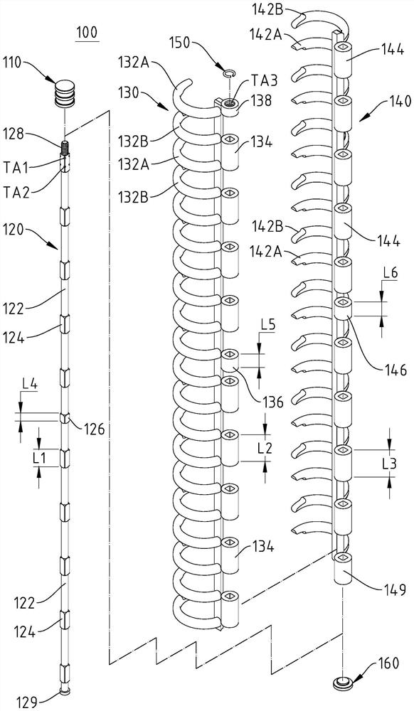
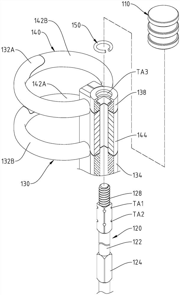
[0048] see Figure 1 to Figure 3 , figure 1 It is a three-dimensional appearance schematic diagram of the multi-ring file hole folder of the present invention. figure 2 It is a three-dimensional exploded schematic view of the multi-ring file hole folder of the present invention. image 3 It is a partial three-dimensional exploded schematic diagram of the multi-ring file hole folder of the present invention. As shown in the figure, in the embodiment of the present invention, for a loose-leaf notebook with multiple loose leaves, the multi-ring file hole folder 100 includes a positioning lock pin 110, a movable central spindle body 120, a first bracket body 130, a second Two br...


PUM


Abstract

The invention provides a multi-ring file hole clamp. The multi-ring file hole clamp comprises a positioning lock pin, a movable center main shaft body, a first support body, a second support body and C-shaped rings. The main body of the movable central main shaft body is formed by staggering a plurality of cylinders and a plurality of rectangles, the top of the movable central main shaft body is connected to the positioning lock pin, and a first positioning groove and a second positioning groove are formed in the surfaces of the rectangles beside the top of the movable central main shaft body. The first support body is provided with a plurality of first semi-rings which are arranged on the first support body at equal intervals, and the first support body is provided with a plurality of first hollow bodies which are arranged on the first support body at equal intervals. The second support body and the first support body are in complementary symmetry, the second support body is provided with a plurality of second semi-rings which are arranged on the second support body at equal intervals, and the second support body is provided with a plurality of second hollow bodies which are arranged on the second support body at equal intervals.

Description

technical field [0001] The invention relates to a file hole folder, in particular to a multi-ring file hole folder for loose-leaf notebooks. Background technique [0002] The binder can be used to fix paper, and its structure mainly includes a front cover, a back cover, and a hole clip between the front cover and the back cover. Put it in a binder. Common hole clips are divided into closed coils and switchable half rings. The former closed coil (such as spiral ring binder) has the characteristics of flexible operation and can be folded in half at 360 degrees, which is convenient for one-handed operation and requires less space. However, because the coil is in a closed state after the finished product is completed, it cannot be opened. , so paper cannot be added or replaced arbitrarily. The latter can open and close the half-ring (such as the loose-leaf ring binder) because the half-ring can be opened and closed, so the user can change its inner pages at will, but because ...

Claims


Application Information

Patent Timeline
Patent Type & Authority Applications(China)
IPC IPC(8): B42F3/04
CPCB42F3/04
Inventor 张智源
Owner 张 智源
Learn More