DDR frequency switching method and device
A technology of frequency switching and frequency, which is applied in the computer field, can solve the problems of frame dropping, inability to adapt to actual application scenarios, and waste of power consumption, etc., and achieve the effect of taking into account power consumption control
- Summary
- Abstract
- Description
- Claims
- Application Information
AI Technical Summary
Benefits of technology
Problems solved by technology
Method used
Image


Examples
Embodiment 1
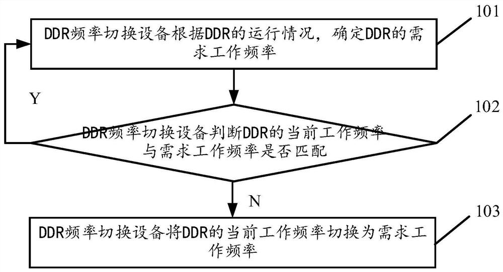
[0084] see figure 1 , figure 1 It is a schematic flowchart of a DDR frequency switching method disclosed in an embodiment of the present invention. Such as figure 1 As shown, the switching method of the DDR frequency may include the following operations:
[0085] 101. The DDR frequency switching device determines the required working frequency of the DDR according to the running condition of the DDR.
[0086] In an optional embodiment, the DDR frequency switching device determines the required operating frequency of the DDR according to the operation of the DDR, including:
[0087] The DDR frequency switching device determines the required operating frequency of the DDR according to the data access to the DDR on the system bus, or,
[0088] The DDR frequency switching device determines the target working state of the DDR;
[0089] The DDR frequency switching device determines the required operating frequency corresponding to the target operating state from the predetermin...
Embodiment 2
[0118] see figure 2 , figure 2 It is a schematic flowchart of another DDR frequency switching method disclosed in the embodiment of the present invention. Such as figure 2 As shown, the switching method of the DDR frequency may include the following operations:
[0119] 201. The DDR frequency switching device determines the required working frequency of the DDR according to the running condition of the DDR.
[0120] 202. The DDR frequency switching device judges whether the current working frequency of the DDR matches the required working frequency. When the judgment result of step 202 is no, step 203 may be triggered, and when the judgment result of step 202 is yes, this process may end, or step 202 or step 201 may be executed again.
[0121] For the specific description of the above-mentioned step 201 and the above-mentioned step 202, reference may be made to the specific description of the above-mentioned step 101 and the above-mentioned step 102, and details will no...
Embodiment 3
[0154] see image 3 , image 3 It is a schematic structural diagram of a DDR frequency switching device disclosed in an embodiment of the present invention. Such as image 3 As shown, the DDR frequency switching device operates on DDR frequency switching equipment, and the DDR frequency switching device may include:
[0155] Determining module 301, is used for determining the required operating frequency of DDR according to the running situation of DDR;
[0156] Judging module 302, for judging whether the current operating frequency of the DDR matches the required operating frequency;
[0157] The switching module 303 is configured to switch the current working frequency of the DDR to the required working frequency when the judging module 302 judges that the current working frequency of the DDR does not match the required working frequency.
[0158] Visible, implemented image 3 The described DDR frequency switching device first determines the required operating frequency...
PUM
 Abstract
Description
Claims
Application Information
 - R&D
- Intellectual Property
- Life Sciences
- Materials
- Tech Scout
- Unparalleled Data Quality
- Higher Quality Content
- 60% Fewer Hallucinations
Browse by: Latest US Patents, China's latest patents, Technical Efficacy Thesaurus, Application Domain, Technology Topic, Popular Technical Reports.
© 2025 PatSnap. All rights reserved.Legal|Privacy policy|Modern Slavery Act Transparency Statement|Sitemap|About US| Contact US: help@patsnap.com