

Handheld device and planar antenna thereof
- Summary
- Abstract
- Description
- Claims
- Application Information
AI Technical Summary
Benefits of technology
Problems solved by technology
Method used
Image

Examples
first embodiment
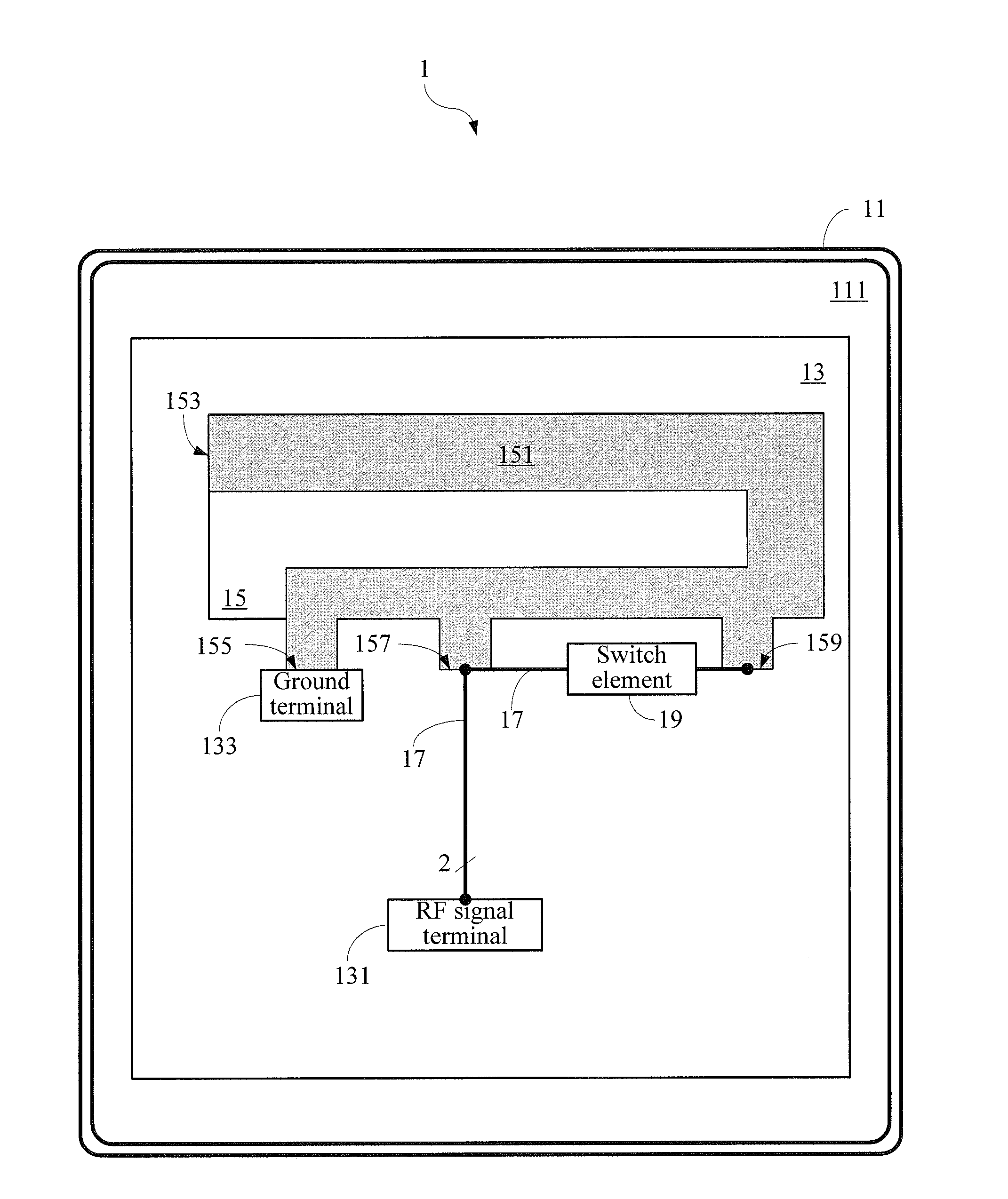
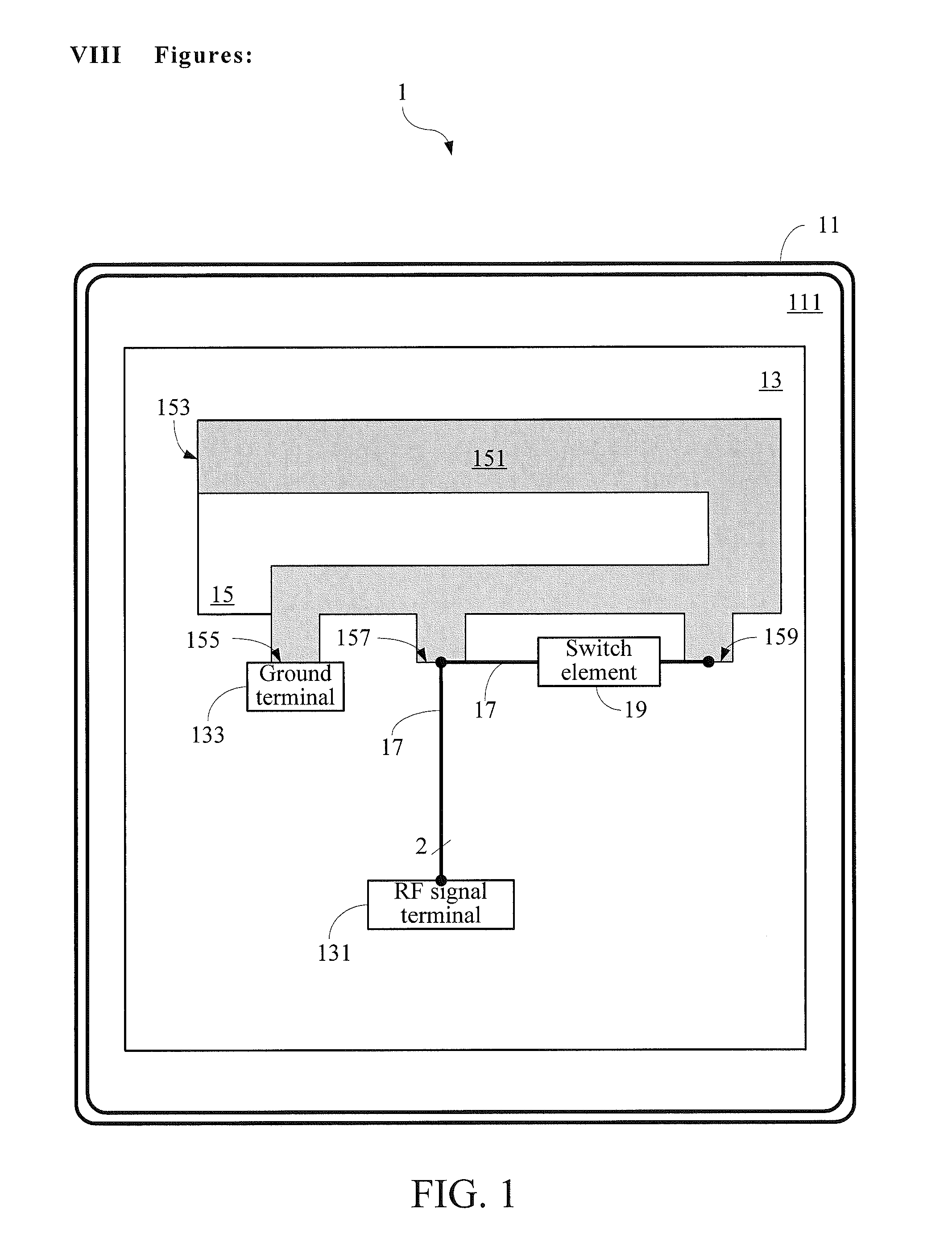
[0033]In reference to FIG. 1, the present invention is a handheld device 1. Specifically, FIG. 1 is a schematic plan view of the handheld device 1. As shown in FIG. 1, the handheld device 1 at least comprises a housing 11, a circuit board 13 and a planar antenna 15. It shall be appreciated that the handheld device 1 in this embodiment may be a handheld electronic device with a wireless transmission function such as a mobile phone, a notebook computer or a tablet computer. In addition, for simplicity of description, other modules (e.g., a touch display module, a communication module, a central processing module, an input module and a power supply module) of the handheld device 1 that are not directly related to the present invention are all omitted from depiction in FIG. 1.
[0034]The housing 11 is adapted to define a receiving space 111 for receiving internal elements and modules of the handheld device 1. The circuit board 13 is disposed in the receiving space 111 and comprises a radi...
second embodiment
[0063]FIG. 4 is a schematic plan view of a handheld device 5 according to the present invention;
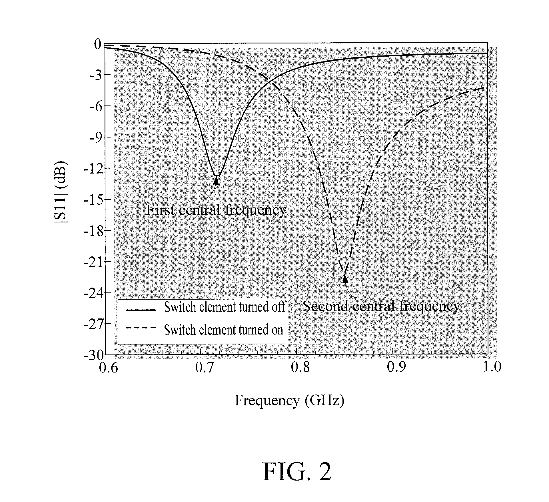
[0064]FIG. 5 is a schematic view illustrating reflection coefficients |S11| of a planar antenna 55 of the handheld device 5 according to the present invention when operating within different frequency bands; and
third embodiment
[0065]FIG. 6 is a schematic plan view of a handheld device 7 according to the present invention.
PUM
 Abstract
Description
Claims
Application Information