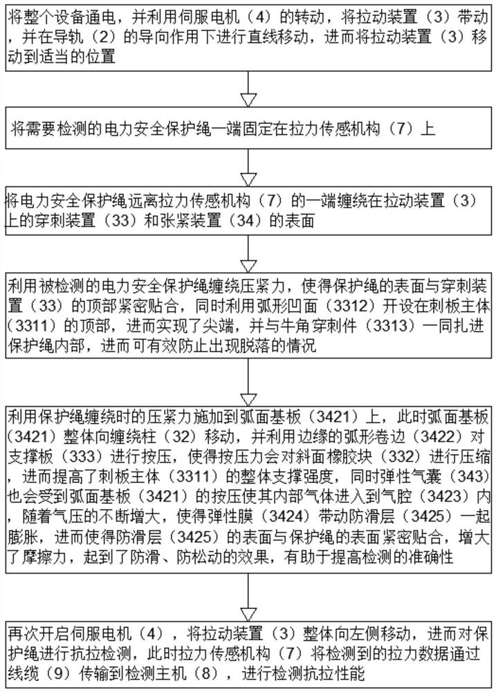
Durability detection equipment and detection method for electric power safety protection rope
A technology for power safety and testing equipment, which is applied in the direction of applying stable tension/pressure to test the strength of materials, measuring devices, and strength characteristics. It can solve problems such as reducing performance, affecting detection efficiency, and inaccurate detection of safety protection ropes. Achieve the effects of improving performance, fast and accurate detection, improving detection efficiency and performance
- Summary
- Abstract
- Description
- Claims
- Application Information
AI Technical Summary
Problems solved by technology
Method used
Image
Examples
Embodiment 1
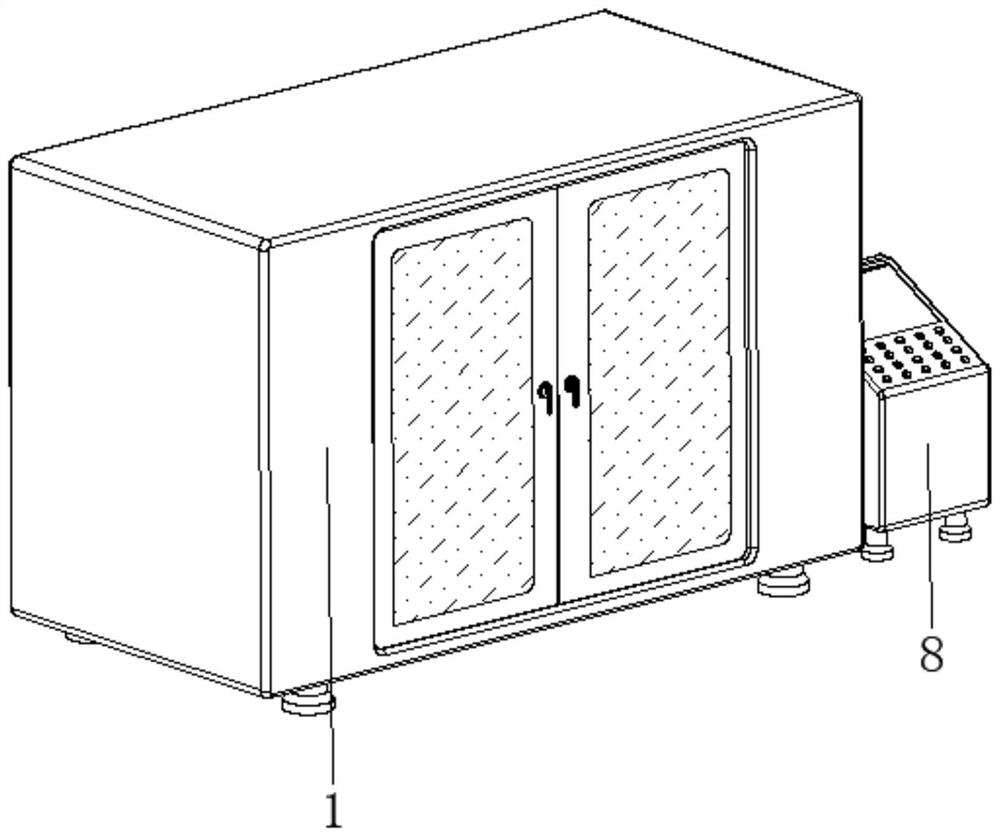
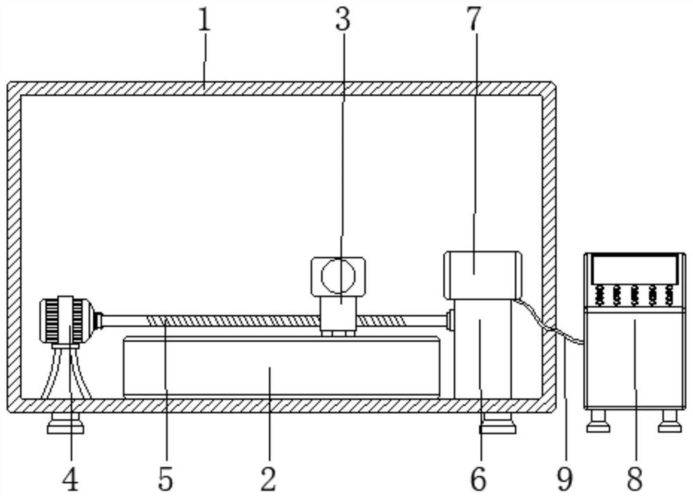
[0039] see Figure 1-Figure 8 , the present invention provides a technical solution: a durability testing device for an electric safety protection rope, comprising a body 1, a guide rail 2, and a pulling device 3, the bottom of the guide rail 2 is fixedly connected to the center of the bottom of the inner wall of the body 1, and the pulling device 3 set on top of rail 2;
[0040] The pulling device 3 is provided with a sliding base 31, a winding column 32, a puncture device 33, and a tensioning device 34. The bottom of the sliding base 31 is slidably connected to the top of the guide rail 2, and one end of the winding column 32 is connected to the surface top of the sliding base 31. One side is fixedly connected, the puncture device 33 is arranged on the surface of the winding column 32, and the tensioning device 34 is arranged on the surface of the winding column 32 and is close to the position of the puncture device 33;
[0041] The bottom side of the inner wall of the body...
Embodiment 2
[0044] The puncture device 33 is provided with a stabbing plate device 331, an inclined-plane rubber block 332, and a support plate 333. The bottom of the stabbing plate device 331 is fixedly connected with the surface of the winding column 32, and one side of the surface of the inclined-plane rubber block 332 is fixed to the surface of the stabbing plate device 331. Connection, one side of the surface of the support plate 333 is fixedly connected with the surface of the inclined rubber block 332 and the side away from the spine device 331, when the pressure plate device 342 is pressed by the winding protection rope, the arc elastic plate 341 will Apply pressure to the arc-shaped elastic plate 341 and the elastic airbag 343. At this time, the arc-shaped elastic plate 341 is deformed by the pressure, and combined with the action force and reaction force, the elastic force of the arc-shaped elastic plate 341 will be reversed by the pressure plate device 342. It is applied to the ...
Embodiment 3
[0048] The tensioning device 34 is provided with an arc elastic plate 341, a pressing plate device 342, and an elastic air bag 343. The end and away from the side of the winding column 32 are fixedly connected, and the elastic airbag 343 is arranged between the two sides corresponding to the surface of the winding column 32 and the surface of the pressing plate device 342 and close to the position of the arc-shaped elastic plate 341. When the pressing plate device 342 is subjected to When the winding protection rope is compressed, the arc-shaped elastic plate 341 will apply pressure to the arc-shaped elastic plate 341 and the elastic airbag 343. At this time, the arc-shaped elastic plate 341 is deformed by the pressure, and combined with the action force and reaction force At this time, the elastic force of the arc-shaped elastic plate 341 will be reversely applied to the wound protection rope through the pressing plate device 342, thereby tensioning the protection rope, thereb...
PUM
 Abstract
Description
Claims
Application Information
 - R&D
- Intellectual Property
- Life Sciences
- Materials
- Tech Scout
- Unparalleled Data Quality
- Higher Quality Content
- 60% Fewer Hallucinations
Browse by: Latest US Patents, China's latest patents, Technical Efficacy Thesaurus, Application Domain, Technology Topic, Popular Technical Reports.
© 2025 PatSnap. All rights reserved.Legal|Privacy policy|Modern Slavery Act Transparency Statement|Sitemap|About US| Contact US: help@patsnap.com


