Positioning and clamping device

A technology of positioning clamping and positioning plate, which is applied in the direction of positioning device, clamping device, clamping, etc., and can solve the problems of inaccurate workpiece positioning and insufficient clamping force of the clamping device.

Pending Publication Date: 2022-05-24
TIANRUN IND TECH CO LTD +1
View PDF10 Cites 0 Cited by
  • Summary
  • Abstract
  • Description
  • Claims
  • Application Information

AI Technical Summary

Problems solved by technology

[0004] Therefore, the technical problem to be solved by the present invention is to overcome the problems of insufficient clamping force of the clamping device and inaccurate positioning of the workpiece in the worm gear processing device in the prior art, and provide a positioning clamping device that realizes positioning of the workpiece from two directions. Advanced positioning and clamping prevents the workpiece from moving sideways and rotating during processing, and improves processing accuracy

Method used


Image

  • Positioning and clamping device
  • Positioning and clamping device
  • Positioning and clamping device

Examples


Embodiment Construction

[0042] The present invention will be further described below with reference to the accompanying drawings and specific embodiments, so that those skilled in the art can better understand the present invention and implement it, but the embodiments are not intended to limit the present invention.

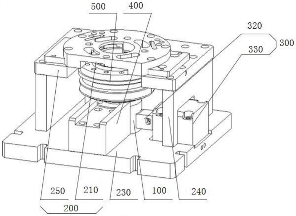
[0043] refer to Figure 1-Figure 4 As shown, a positioning and clamping device of the present invention is characterized in that it includes:

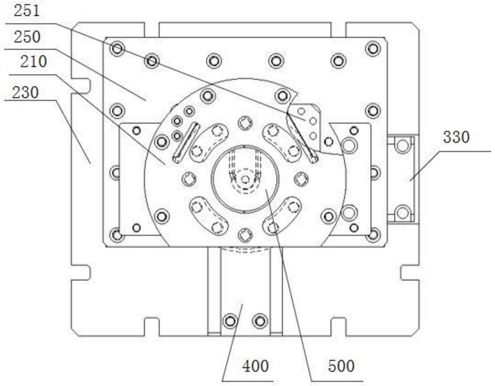
[0044] The carrier 100 is used to carry the workpiece 500;

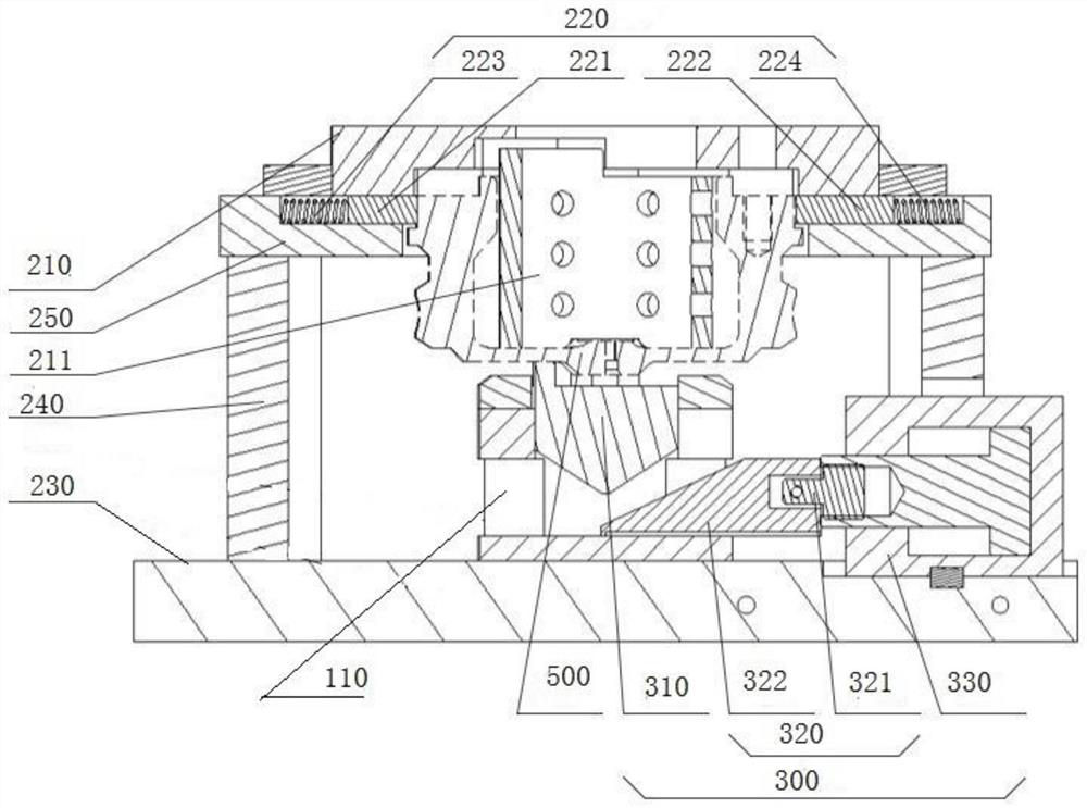
[0045] The first positioning mechanism 200 is arranged above the carrier 100 and includes a positioning plate 210 corresponding to the carrier 100 and a clamping mechanism 220 arranged on the side of the workpiece. The clamping mechanism 220 reciprocates in the direction of the workpiece 500 , to realize the clamping and fixing of the workpiece 500;

[0046] The clamping mechanism 220 is arranged in the carrier 100 and is slidably connected with the carrier 100 . The clamping mechan...


PUM


Abstract

The invention relates to a positioning and clamping device which comprises a carrying table used for carrying a workpiece; the first positioning mechanism is arranged above the carrying table and comprises a positioning plate arranged corresponding to the carrying table and a clamping mechanism arranged on the side face of the workpiece, and the clamping mechanism reciprocates in the direction of the workpiece to clamp and fix the workpiece; and the second positioning mechanism is arranged in the carrying table and is in sliding connection with the carrying table, the second positioning mechanism slides in the direction from the carrying table to the positioning plate, and when the second positioning mechanism slides, the workpiece is pushed to abut against the positioning plate. The workpiece is positioned and clamped in two directions, lateral movement and rotation of the workpiece in the machining process are prevented, and the machining precision is improved.

Description

technical field [0001] The invention relates to the technical field of processing equipment, in particular to a positioning and clamping device. Background technique [0002] Worm gears and worms are often used to transmit motion and power between two staggered shafts. The worm gears and worms are equivalent to gears and racks in their mid-plane. They need to be drilled during the processing of the worm gear. At the same time, in order to ensure the drilling of the worm gear Accuracy, the worm gear generally needs to be fixed and then punched, so the fixing of the worm gear needs to be very precise. [0003] In the existing worm gear processing device, the four sides of the worm gear are clamped and fixed by the clamping device, but during the punching process, due to the impact force of the punching, the clamps in the clamping device are easy to move during the processing process, and it is easy to Cause the inclination of the worm gear, thereby affecting the machining acc...

Claims


Application Information

Patent Timeline
IPC IPC(8): B23Q3/00B23Q3/18
CPCB23Q3/00B23Q3/18B23Q2703/10Y02P70/50
Inventor 李忠民韩吉超杜武飞
Owner TIANRUN IND TECH CO LTD
Why Eureka
Try Eureka