Tunnel collapse treatment process and structure
A technology for processing technology and tunnels, which is applied in the direction of tunnels, tunnel linings, earthwork drilling and mining, etc., and can solve problems such as geological secondary landslides, hidden dangers, and anchor-spray failure safety, so as to reduce safety, impact, and The effect of safety hazards
- Summary
- Abstract
- Description
- Claims
- Application Information
AI Technical Summary
Problems solved by technology
Method used
Image

Examples
Embodiment 1
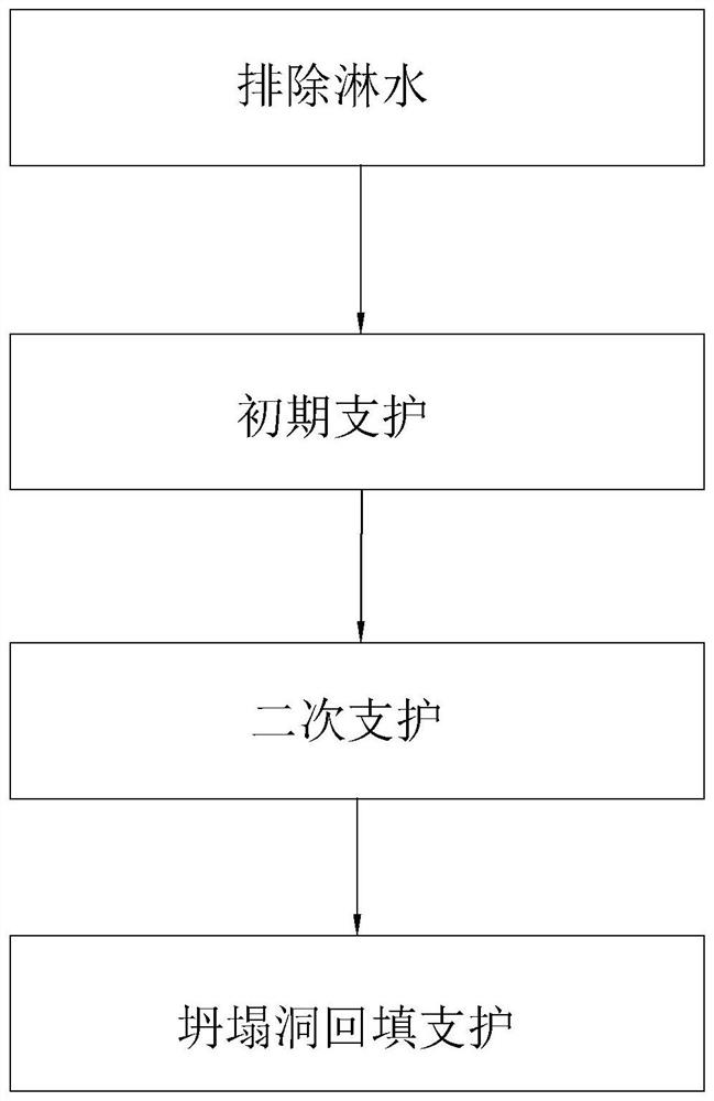
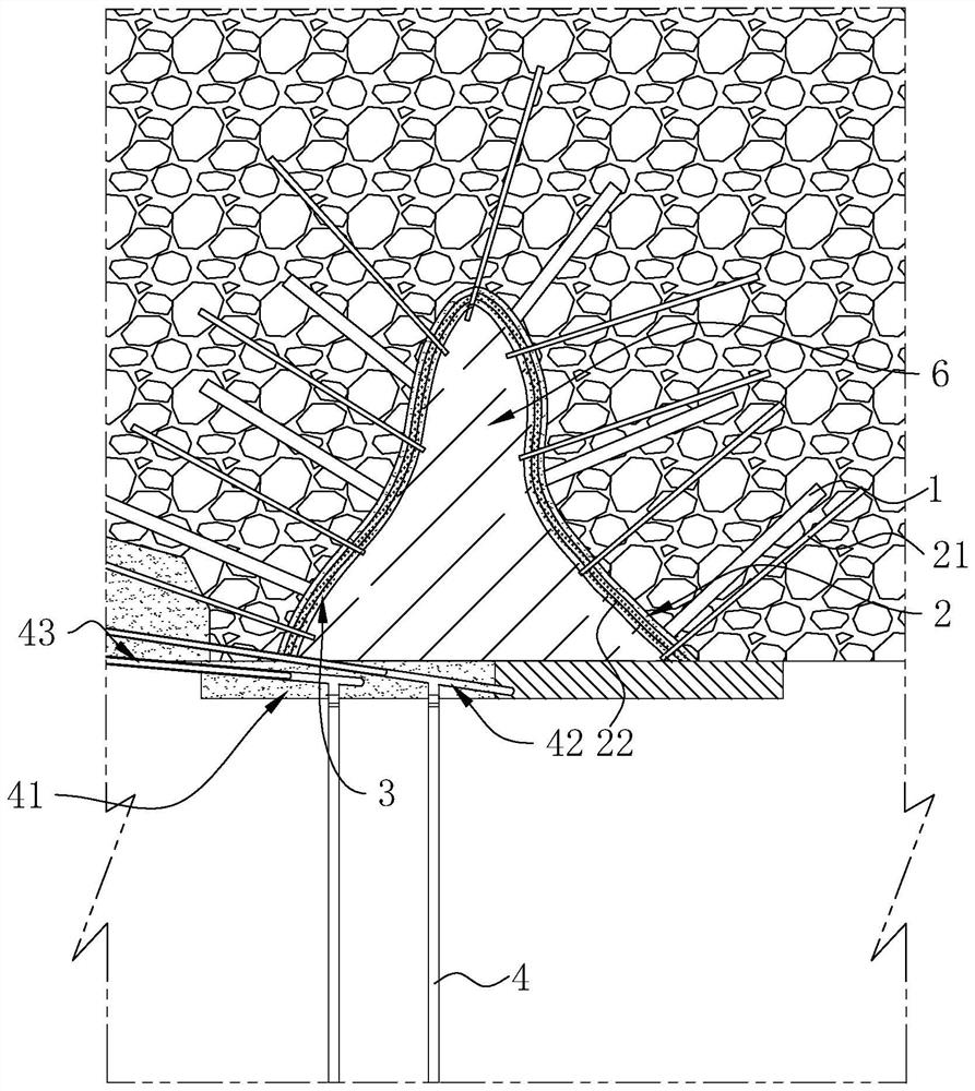
[0044] refer to figure 1 and figure 2 , a tunnel collapse treatment process includes the following steps:
[0045] S1. Exclusion of water spray: A nozzle is installed in the collapsed cave or at the bottom, and the inner wall of the collapsed cave is scoured by high-pressure water through the nozzle, and the unstable rocks and earthwork in the collapsed cavern are cleaned up, thereby reducing the rock or earthwork in the subsequent construction process. The possibility of secondary landslides can effectively increase the safety in the subsequent construction process.
[0046] After the collapsed hole is stabilized, that is, after the initial infiltration and drainage of the water, a plurality of drainage holes are opened on the inner wall of the collapsed hole, and then a flushing pipe 1 is inserted in the drainage hole, and the flushing pipe 1 is inserted into the top wall of the drainage hole 30-60cm; Then, high-pressure water is poured into the collapsed cave through the...
Embodiment 2
[0059] refer to Figure 4 The difference between this embodiment and Embodiment 1 is that the specific steps of step S4 are as follows: when backfilling the collapsed hole with the support plate 41 as the construction platform, set up a plurality of filling grouting pipes distributed in sequence from top to bottom in the collapsed hole 5. The filling and grouting pipes 5 are annular and are respectively fixed and connected to different initial bolts 21, and the filling and grouting pipes 5 are arranged horizontally. The grouting pipe 5 can be made of an ordinary concrete grouting guide pipe, or the grouting pipe 5 can be formed by opening a grouting hole on the side wall of the pipe.
[0060] Further, the plurality of filling and grouting pipes 5 are connected with pump pipes 51 passing through the collapsed holes, so as to be used for pouring concrete into the filling and grouting pipes 5 . A filling valve 52 for controlling the passage of concrete is provided between the fi...
Embodiment 3
[0062] refer to Figure 5 The difference between this embodiment and Embodiment 1 is that the specific steps of step S4 are as follows: the support plate 41 is used as a construction platform in the collapsed hole, and the reinforcement formwork is hung on the initial anchor rod 21 at the top, and the reinforcement formwork is placed in the reinforcement formwork. The reinforcing support plate 44 is formed by pouring concrete, and after the reinforcing support plate 44 is cured, the reinforcing formwork located below is removed.
[0063] A reinforcing formwork is hung under the formed reinforcing support plate 44, and the next reinforcing support plate 44 is formed through the reinforcing formwork, thereby forming a plurality of reinforcing support plates 44 in sequence from top to bottom in the collapsed hole. Finally, the opening formed by the support plate 41 and the edge of the opening of the collapsed hole is closed. In order to achieve the support for the inside of the ...
PUM
 Abstract
Description
Claims
Application Information
 - R&D
- Intellectual Property
- Life Sciences
- Materials
- Tech Scout
- Unparalleled Data Quality
- Higher Quality Content
- 60% Fewer Hallucinations
Browse by: Latest US Patents, China's latest patents, Technical Efficacy Thesaurus, Application Domain, Technology Topic, Popular Technical Reports.
© 2025 PatSnap. All rights reserved.Legal|Privacy policy|Modern Slavery Act Transparency Statement|Sitemap|About US| Contact US: help@patsnap.com