Operating table and method for controlling operating table

A technology for operating tables and controllers, applied in the field of operating tables, can solve problems such as inability to achieve component posture, limited range of motion, and risk of collisions

Pending Publication Date: 2022-05-27
TRUMPF MEDIZIA SYST GMBH CO KG
View PDF0 Cites 0 Cited by
  • Summary
  • Abstract
  • Description
  • Claims
  • Application Information

AI Technical Summary

Problems solved by technology

Therefore, if the actual configuration of the operating table does not conform to the standard geometric collision model, there may be a risk of collision, or a limited range of motion, preventing the desired pose of the part from being achieved

Method used


Image

  • Operating table and method for controlling operating table
  • Operating table and method for controlling operating table

Examples


Embodiment Construction

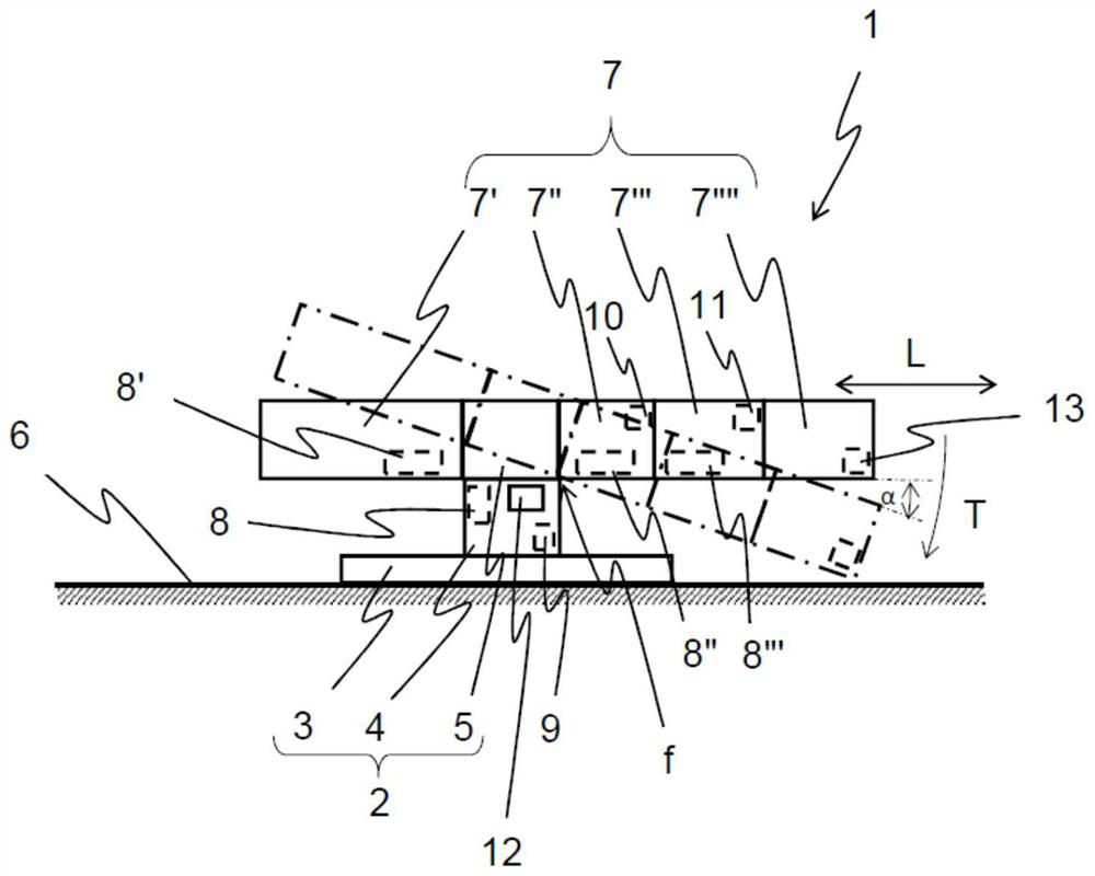
[0051] figure 1 A schematic diagram of a first configuration of the operating table 1 is shown. The operating table 1 includes a base 2 . The base 2 includes a chassis 3 , a column 4 and a column head 5 . The base 2 is supported by the floor as the support surface 6 . In an alternative embodiment, the base 2 does not include the chassis 3 but the columns 4 are fixedly attached to the support surface 6 . In a further alternative embodiment, the base 2 comprises a column head 5 integrated into the column 4 .

[0052] Furthermore, the operating table 1 comprises several parts 7 that are movable relative to each other and the base 2 . In particular, the operating table 1 comprises as several components 7 a leg 7', a back plate 7", an upper back plate 7"' and a head plate 7"". Several parts 7 form the table top of the operating table 1 . The longitudinal direction of the table top is L.

[0053] In this embodiment, some of the several components 7, namely the legs 7', the ba...


PUM


Abstract

The operating table (1) comprises a base (2), a component (7) and a controller (9). The controller (9) is configured to store a geometric impact model comprising an object model dataset of the component (7), the base (2) and the support surface (6) and a motion calculation dataset of the base (2) and the component (7). The controller (9) is configured to execute an anti-collision algorithm defining a range of motion of the base (2) and the component (7) based on a specific geometric collision model and to control the drives (8 ', 8' ', 8' ') to move the base (2) and the component (7) within the defined range of motion to prevent a collision. The controller (9) is configured to store the initial geometric collision model of the defined configuration and to adapt the initial geometric collision model to the actual geometric collision model according to the actual configuration.

Description

technical field [0001] The present disclosure relates to an operating table and a method for controlling the operating table, in particular to an operating table and a method for controlling an operating table with an anti-collision function. Background technique [0002] Operating tables with a crash-proof function are known. For example, EP3667675A1 discloses a medical instrument, especially an operating table with such an anti-collision function. Due to this feature, collisions between parts of the operating table and other parts and the floor are prevented. For this function, the configuration of the operating table is reproduced by a virtual bounding box, in addition, the current position and orientation of the bounding box is used to determine the impending collision of the real parts of the operating table. [0003] However, this collision avoidance function is based on a standard geometric collision model representing the basic configuration of the operating table....

Claims


Application Information

Patent Timeline
IPC IPC(8): A61G13/02A61G13/04A61G13/08A61G13/10G06T7/70G16H40/63
CPCA61G13/02A61G13/04A61G13/10G16H40/63G06T7/70A61G13/08G06T2210/21G06T2210/12A61G2203/10A61G2203/72A61G2203/726G16H20/40
Inventor M·科勒M·雅格
Owner TRUMPF MEDIZIA SYST GMBH CO KG
Why Eureka
Try Eureka