A liquid adding device and liquid adding method

An equipment and liquid tank technology, which is applied in the field of liquid addition equipment and liquid addition, can solve the problems of lack of liquid addition equipment and uniform liquid addition equipment, and achieve the effects of improving convenience, precise liquid addition, and strong usability.

Active Publication Date: 2022-07-05
常州米柔科技发展有限公司
View PDF7 Cites 0 Cited by
  • Summary
  • Abstract
  • Description
  • Claims
  • Application Information

AI Technical Summary

Problems solved by technology

[0004] The purpose of the present invention is to provide a liquid-feeding device and its liquid-feeding method, which solves the problem of lacking a liquid-feeding device with uniform liquid-feeding in the prior art

Method used


Image

  • A liquid adding device and liquid adding method
  • A liquid adding device and liquid adding method
  • A liquid adding device and liquid adding method

Examples


Embodiment 1

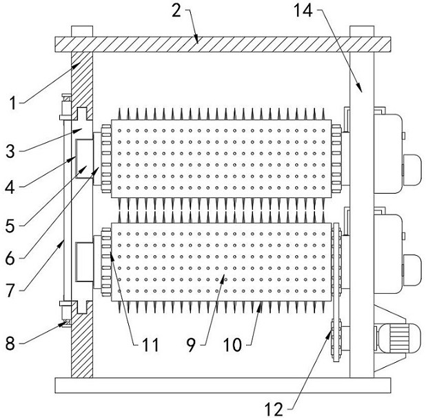
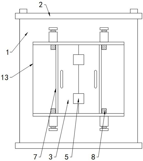
[0036] refer to Figure 1-5 , a liquid dosing device, including:

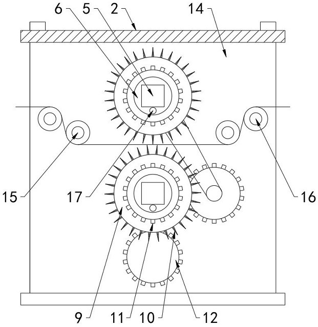
[0037] The top plate 2, the left side plate 1 and the right side plate 14 are respectively installed on both sides of the bottom of the top plate 2, the bottom of the left side plate 1 and the right side plate 14 is installed with a base, and the left side plate 1 and the right side plate 14 are respectively installed with Lead-in roller 15 and lead-out roller 16;

[0038] The fixed shaft 6 is provided with at least one group, and each group is provided with two. One end of the two fixed shafts 6 is fixedly connected to the right side plate 14, and the other end is detachably installed with the left side plate 1. The fixed shaft 6 A liquid storage cavity is arranged inside, and a positioning box 21 is movably arranged on the outer wall of the liquid storage cavity. The upper end surface of the positioning box 21 is an open end, and the lower end surface of the positioning box 21 is provided with a plurality of...

Embodiment 2

[0044] refer to Figure 1-5 , a liquid dosing device, including:

[0045] The top plate 2, the left side plate 1 and the right side plate 14 are respectively installed on both sides of the bottom of the top plate 2, the bottom of the left side plate 1 and the right side plate 14 is installed with a base, and the left side plate 1 and the right side plate 14 are respectively installed with Lead-in roller 15 and lead-out roller 16;

[0046] The fixed shaft 6 is provided with at least one group, and each group is provided with two. One end of the two fixed shafts 6 is fixedly connected to the right side plate 14, and the other end is detachably installed with the left side plate 1. The fixed shaft 6 A liquid storage cavity is arranged inside, and a positioning box 21 is movably arranged on the outer wall of the liquid storage cavity. The upper end surface of the positioning box 21 is an open end, and the lower end surface of the positioning box 21 is provided with a plurality of...

Embodiment 3

[0053] refer to Figure 1-5 , a liquid dosing device, including:

[0054] The top plate 2, the left side plate 1 and the right side plate 14 are respectively installed on both sides of the bottom of the top plate 2, the bottom of the left side plate 1 and the right side plate 14 is installed with a base, and the left side plate 1 and the right side plate 14 are respectively installed with Lead-in roller 15 and lead-out roller 16;

[0055] The fixed shaft 6 is provided with at least one group, and each group is provided with two. One end of the two fixed shafts 6 is fixedly connected to the right side plate 14, and the other end is detachably installed with the left side plate 1. The fixed shaft 6 A liquid storage cavity is arranged inside, and a positioning box 21 is movably arranged on the outer wall of the liquid storage cavity. The upper end surface of the positioning box 21 is an open end, and the lower end surface of the positioning box 21 is provided with a plurality of...


PUM


Abstract

The invention relates to the technical field of roll-type liquid addition equipment, in particular to a liquid addition device and a liquid addition method thereof, which solves the problem of the lack of a liquid addition device with uniform liquid addition in the prior art. A liquid adding device includes: a top plate, a fixed shaft and a liquid adding roller, a left plate and a right plate are respectively installed on both sides of the bottom of the top plate, one end of the fixed shaft is fixedly connected with the right plate, and the other end can be connected with the left plate. Removal and installation, the detachable movable sleeve of the dosing roller is set outside the fixed shaft, and there are a plurality of microneedles in the array on the dosing roller. In the present invention, the positioning box in the fixed shaft is driven to abut against the bottom end of the microneedle, so that during the rotation of the liquid adding roller, the positioning box positions and adds liquid to the microneedle in contact with the paper, and the inside of the fixed shaft is subjected to the pressure of the liquid adding tank. The liquid output and speed are controlled, so that the micro-needles are in uniform contact with the upper and lower end faces of the paper and the liquid is added. Moreover, the size of the micro-needles is a certain size. By controlling the pressure, the effect of precise control of the liquid addition can be achieved.

Description

technical field [0001] The invention relates to the technical field of roll-type liquid addition equipment, in particular to a liquid addition device and a liquid addition method thereof. Background technique [0002] The existing rubber roller is the most common type of roller liquid feeding equipment. The rubber roller can be divided into: papermaking rubber roller, printing and dyeing rubber roller, printing rubber roller, grain hulling rubber roller, metallurgical rubber roller and oil printing rubber roller, etc.; according to the surface The form can be divided into: flat roll and pattern rubber roll; according to the material can be divided into: butyl rubber roll, nitrile rubber roll, polyurethane rubber roll and silicone rubber rubber roll, etc. The rubber roller is generally composed of outer rubber, hard rubber layer, metal core, roll neck and ventilation holes. Its processing includes roll core sandblasting, bonding treatment, glue forming, cloth wrapping, wire w...

Claims


Application Information

Patent Timeline
Patent Type & Authority Patents(China)
IPC IPC(8): B05C5/02B05C11/10B05C11/11
CPCB05C5/0275B05C11/1013B05C11/10B05C11/11Y02E60/10
Inventor 徐斌刘晓成
Owner 常州米柔科技发展有限公司
Why Eureka
Try Eureka