Vehicle-mounted camera cleaning device based on small swing brush

A cleaning device and camera technology, applied in the field of vehicle cameras, can solve problems such as failure to work normally, dirty external cameras, etc., and achieve the effect of simple, stable and efficient structure, and reduce potential safety hazards

Pending Publication Date: 2022-05-27
英博超算(南京)科技有限公司
View PDF0 Cites 0 Cited by
  • Summary
  • Abstract
  • Description
  • Claims
  • Application Information

AI Technical Summary

Problems solved by technology

[0003] The invention proposes a vehicle-mounted camera cleaning device based on a small swinging brush, which solves the problem that the existing vehicle external cameras are susceptible to dirt and cannot work normally

Method used


Image

  • Vehicle-mounted camera cleaning device based on small swing brush
  • Vehicle-mounted camera cleaning device based on small swing brush
  • Vehicle-mounted camera cleaning device based on small swing brush

Examples


Embodiment 1

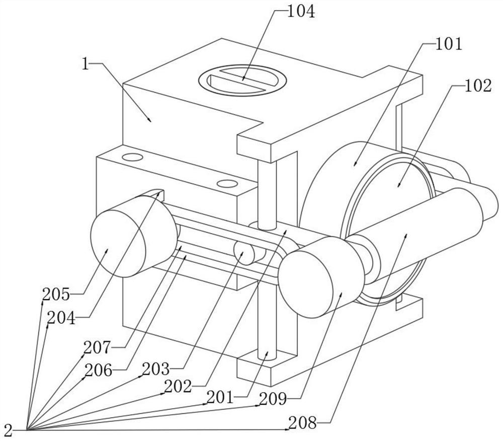
[0037] refer to Figure 1-Figure 8 , a vehicle-mounted camera cleaning device based on a small pendulum brush, comprising a housing 1 and a camera 3, the camera 3 is installed in the housing 1, and the outer wall of the housing 1 is provided with a protective cover 101 and a lens 102 for the camera 3 to shoot, The outer wall of the housing 1 is also installed with a swing brush mechanism 2 for cleaning the lens 102;

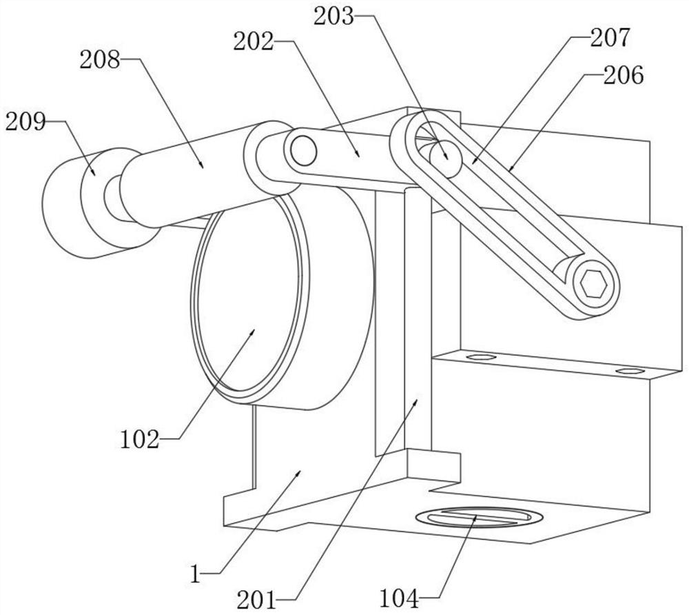
[0038] The swing brush mechanism 2 includes a roller brush 208 and a second motor 209 for cleaning the lens 102, and also includes a first motor 205, a connecting rod 206, a guide rod 201 and a slider 202 for driving the roller brush 208 to swing. The guide rods 201 are located on both sides of the protective cover 101 , the slider 202 is slidably connected to the guide rod 201 , and both ends of the roller brush 208 are rotatably connected to the two sets of sliders 202 , and the first motor 205 passes through The bracket 204 is connected to the housing 1, and ...

Embodiment 2

[0047] In Example 1, the first motor 205 drives the roller brush 208 to swing to the obstruction area, starts the second motor 209, and drives the roller brush 208 to rotate to remove the obstruction. The first motor 205 is only responsible for swinging the roller brush 208 to the obstruction area, Instead of directly participating in the cleaning of the obstructions, the second motor 209 drives the roller brush 208 to rotate and clean, which belongs to fixed-point cleaning. The difference between Embodiment 2 and Embodiment 1 is that the second motor 209 controls the roller brush 208 not to rotate, completely The roller brush 208 is driven by the first motor 205 to repeatedly oscillate to erase the obstructions on the surface of the lens 102 . This cleaning method directly cleans the entire lens 102 without calculating the position of the obstruction, which can save CPU computing power.

Embodiment 3

[0049]The difference from Embodiment 1 and Embodiment 2 is that the first motor 205 and the second motor 209 work at the same time, and the roller brush 208 is driven to rotate while wiping the surface of the lens 102. At this time, the cleaning ability of the swing brush mechanism 2 is relatively strong. , the stubborn dirt that is difficult to remove in Example 1 and Example 2 can be removed.

[0050] The working principle of the swing brush mechanism 2 of the device: the device drives the connecting rod 206 to deflect through the first motor 205, and the deflected connecting rod 206 drives the sliding block 202 to slide along the guide rod 201 through the sliding groove 207 and the short column 203, and passes the sliding block 202 The second motor 209 and the roller brush 208 are driven to swing. During this process, the slider 202 is restricted by the guide rod 201 , so that the moving path of the roller brush 208 is always in close contact with the lens 102 .


PUM


Abstract

The invention discloses a vehicle-mounted camera cleaning device based on a small swing brush, relates to the field of vehicle-mounted cameras, and provides the following scheme for solving the problem that an existing vehicle external camera is prone to being contaminated and cannot work normally: the vehicle external camera cleaning device comprises a shell and a camera, the camera is mounted in the shell, and the shell is internally provided with a motor; the outer wall of the shell is provided with a protective cover for shooting of the camera and a lens, the outer wall of the shell is further provided with a swing brush mechanism for cleaning the lens, the swing brush mechanism comprises a rolling brush for cleaning the lens and a second motor, and the swing brush mechanism further comprises a first motor for driving the rolling brush to swing, a connecting rod, a guide rod and a sliding block; the two guide rods are located on the two sides of the protective cover, the sliding blocks are slidably connected with the guide rods, the two ends of the rolling brush are rotationally connected with the two sliding blocks, and the first motor is connected with the shell through a support. The vehicle external camera is novel in structure, and the problem that an existing vehicle external camera cannot work normally due to the fact that the existing vehicle external camera is prone to being dirty is effectively solved.

Description

technical field [0001] The invention relates to the field of vehicle-mounted cameras, in particular to a vehicle-mounted camera cleaning device based on a small pendulum brush. Background technique [0002] The safety configuration on the car is changing with each passing day. With the development of related technologies, more and more cameras are installed on the car body to detect the surrounding environment of the vehicle, so as to achieve the purpose of providing driving environment information, records and danger warning. The driving environment is complex and changeable, especially in dusty, rainy and snowy weather, the camera lens is easily dirty, making it unable to work normally. Therefore, in order to solve the above problems, we propose a vehicle camera cleaning device based on a small pendulum brush. SUMMARY OF THE INVENTION [0003] The invention proposes a vehicle-mounted camera cleaning device based on a small swing brush, which solves the problem that the e...

Claims


Application Information

Patent Timeline
Patent Type & Authority Applications(China)
IPC IPC(8): B08B1/00B08B1/04B08B13/00
CPCB08B1/002B08B1/04B08B13/00
Inventor 关锐田锋付玉堂
Owner 英博超算(南京)科技有限公司
Why Eureka
Try Eureka