Liquid rocket engine pintle injector with stable flow structure
A liquid rocket, stable flow technology, applied in the aerospace field, which can solve problems such as performance changes, amplifying pressure fluctuations in the combustion chamber, and intensifying engine vibration.
- Summary
- Abstract
- Description
- Claims
- Application Information
AI Technical Summary
Problems solved by technology
Method used
Image
Examples
Embodiment 1
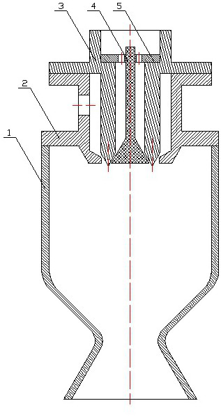
[0048] like figure 1 As shown, a liquid rocket engine needle-bolt injector with a stable flow structure shown in this embodiment, the outer nozzle contains a stable flow structure, and the inner nozzle does not contain a stable flow structure, including the injector housing 2, the needle Valve 3, support plate 4 and needle bolt 5, the side of the injector housing 2 is provided with an opening, the top of the needle valve 3 is provided with an opening, the support plate 4 is fixed inside the needle valve 3, and the needle bolt 5 is fixed on the support plate 4.
[0049] In the above structure, the outer ring propellant enters from the side opening of the injector housing 2 and is sprayed into the combustion chamber through the outer nozzle. The outer nozzle has a structure in which the flow area first decreases and then increases. The smallest flow area is the outer nozzle throat If the outer ring propellant is in liquid state, cavitation will occur at the throat of the outer n...
Embodiment 2
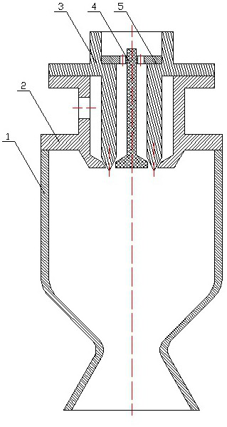
[0052] like figure 2 As shown, a liquid rocket engine needle-bolt injector with a stable flow structure shown in this embodiment, the inner nozzle contains a stable flow structure, and the outer nozzle does not contain a stable flow structure, including the injector housing 2, the needle Valve 3, support plate 4 and needle bolt 5, the side of the injector housing 2 is provided with an opening, the top of the needle valve 3 is provided with an opening, the support plate 4 is fixed inside the needle valve 3, and the needle bolt 5 is fixed on the support plate 4.
[0053] In the above structure, the outer ring propellant enters from the side opening of the injector housing 2 and is injected into the combustion chamber through the outer nozzle; the inner ring propellant enters through the top opening of the needle valve 3 and is injected into the combustion chamber through the inner nozzle, wherein the inner nozzle It contains a structure in which the flow area first decreases an...
Embodiment 3
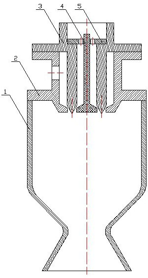
[0056] like image 3 As shown, a liquid rocket engine needle injector with a stable flow structure shown in this embodiment, both the outer nozzle and the inner nozzle contain a stable flow structure, including the injector housing 2, the needle valve 3, the support The plate 4 and the needle bolt 5, the side of the injector housing 2 is provided with an opening, the top of the needle valve 3 is provided with an opening, the support plate 4 is fixed inside the needle valve 3, and the needle bolt 5 is fixed on the support plate 4.
[0057] In the above structure, the outer ring propellant enters from the side opening of the injector housing 2 and is injected into the combustion chamber through the outer nozzle. Throat, if the propellant in the outer ring is liquid, cavitation occurs at the throat of the outer nozzle. If it is in a vapor state, the speed of sound is maintained at the throat of the outer nozzle, and the outer nozzle plays a role in stabilizing the flow of the prope...
PUM
 Abstract
Description
Claims
Application Information
 - R&D
- Intellectual Property
- Life Sciences
- Materials
- Tech Scout
- Unparalleled Data Quality
- Higher Quality Content
- 60% Fewer Hallucinations
Browse by: Latest US Patents, China's latest patents, Technical Efficacy Thesaurus, Application Domain, Technology Topic, Popular Technical Reports.
© 2025 PatSnap. All rights reserved.Legal|Privacy policy|Modern Slavery Act Transparency Statement|Sitemap|About US| Contact US: help@patsnap.com


