Precise combination bearing with adjustable pretightening force
A combined bearing and adjustable technology, applied in the direction of ball bearings, shafts and bearings, bearing components, etc., can solve the problems of adjustment and inconvenient use, and achieve the effect of easy installation and disassembly, and quick assembly
- Summary
- Abstract
- Description
- Claims
- Application Information
AI Technical Summary
Problems solved by technology
Method used
Image

Examples
Embodiment Construction
[0029] The implementation mode of the present invention is illustrated by specific specific examples below, and those who are familiar with this technology can easily understand other advantages and effects of the present invention from the contents disclosed in this description. Obviously, the described embodiments are a part of the present invention. , but not all examples. Based on the embodiments of the present invention, all other embodiments obtained by persons of ordinary skill in the art without making creative efforts belong to the protection scope of the present invention.
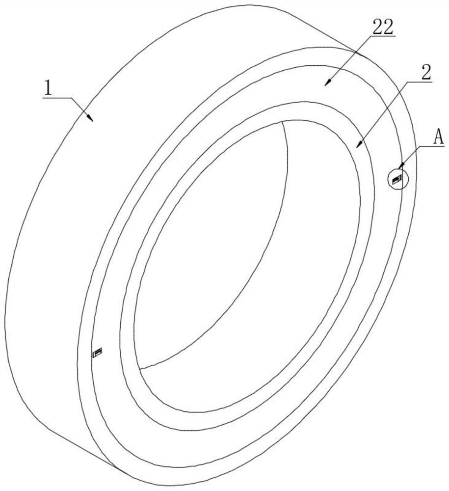
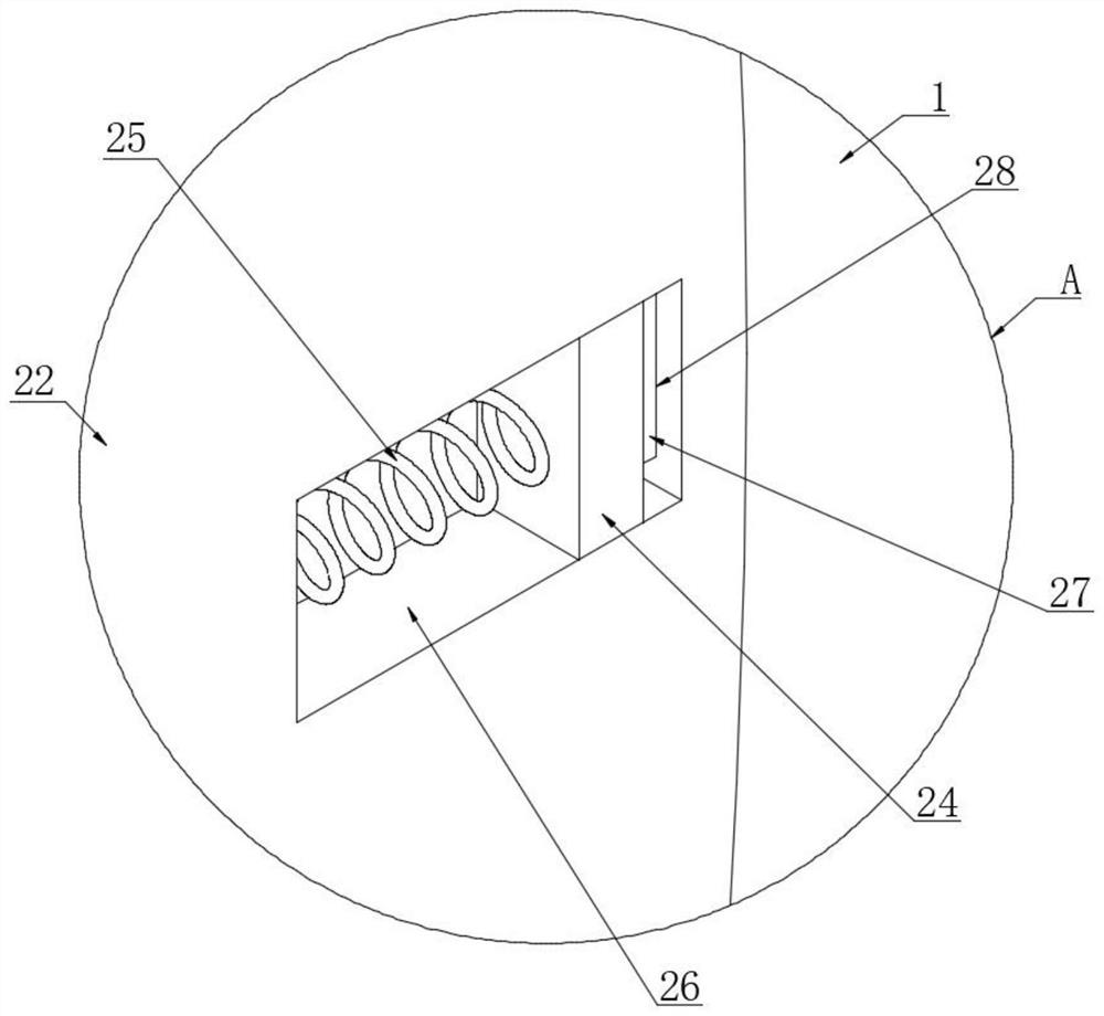
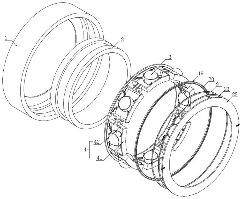
[0030] Refer to attached Figure 1-7 , a preload adjustable precision combined bearing provided by the present invention includes a bearing outer ring 1, a bearing inner ring 2 is coaxially arranged on the inner side of the bearing outer ring 1, and multiple bearings are arranged between the bearing outer ring 1 and the bearing inner ring 2. A ball 3, a plurality of balls 3 are distributed in a ...
PUM
 Abstract
Description
Claims
Application Information
PatSnap Eureka turns technology decisions into work you can execute. Powered by our Innovation Knowledge Graph, it runs expert workflows across engineering, life sciences, materials and intellectual property. Get your review-ready output in minutes.


