Connecting structure of suspension bridge cable clamp and main cable and construction technology

A technology for connecting structures and suspension bridges, which is applied in the direction of suspension bridges, bridges, and bridge construction. It can solve the problems of PE sheath tearing, large force component of cable clips sliding down, and cable clips slipping, so as to achieve high friction and prevent water vapor. Intrusion and convenient construction

Pending Publication Date: 2022-06-03
WUXI MUNICIPAL DESIGN INST
View PDF6 Cites 0 Cited by
  • Summary
  • Abstract
  • Description
  • Claims
  • Application Information

AI Technical Summary

Problems solved by technology

When the longitudinal slope angle of the main cable is large, and the force value of the boom or sling is large, the force component of the cable clip slides is large. Since the tensile fracture strength of the PE material is small, under the action of a large slide force, the PE Potential for the sheath to tear, causing the clip to slip
Therefore, the cable clamp method that directly clamps the PE surface has certain limitations on the longitudinal slope of the main cable and the force value of the boom or sling.

Method used


Image

  • Connecting structure of suspension bridge cable clamp and main cable and construction technology
  • Connecting structure of suspension bridge cable clamp and main cable and construction technology
  • Connecting structure of suspension bridge cable clamp and main cable and construction technology

Examples


Embodiment 1

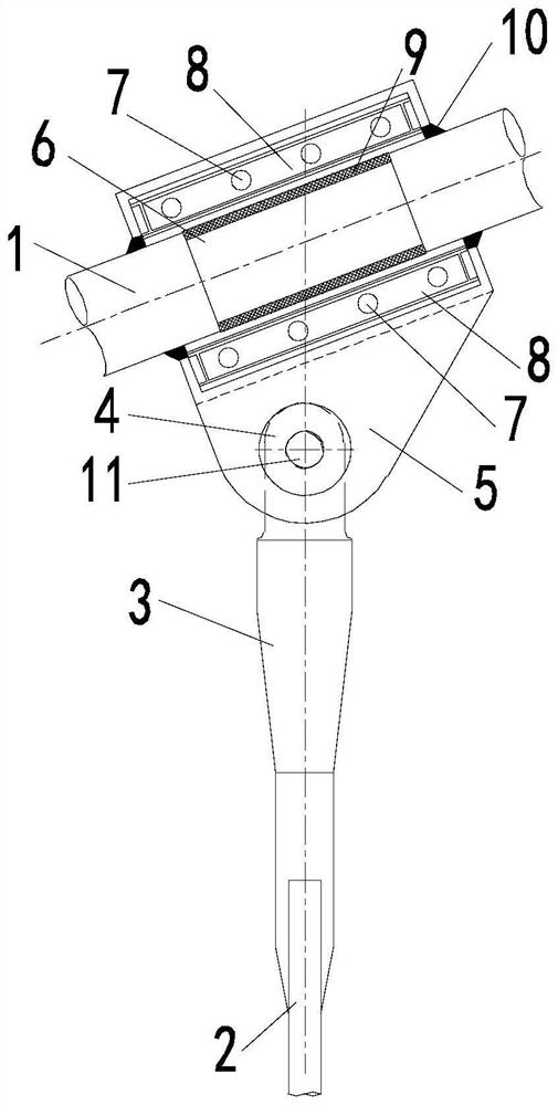
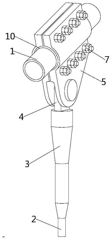
For this, refer to Figure 1 to Figure 4 As shown in the figure, a connection structure between a cable clamp of a suspension bridge and a main cable includes a main cable 1, a suspension cable 2, an anchor head 3 and an ear plate 4, and the suspension cable 2 and the ear plate 4 are respectively connected to both ends of the anchor head 3, The main cable 1 is a finished cable with a PE sheath, and also includes a zinc washer 9 and two connected splints 5. The splint 5 is rotatably connected to the ear plate 4, and the splint 5 includes a semi-circular arc shape in cross section. accommodating cavity, the zinc washer 9 is a semi-circular arc-shaped structure in cross section, the outer arc surface of the zinc washer 9 fits with the inner arc surface of the accommodating cavity, and the main cable 1 includes stripping PE. (Polyethylene) main cable surface 6, the main cable surface 6 after peeling off PE and the inner arc surface of the zinc washer 9 fit. By arranging the zinc w...

Embodiment 2

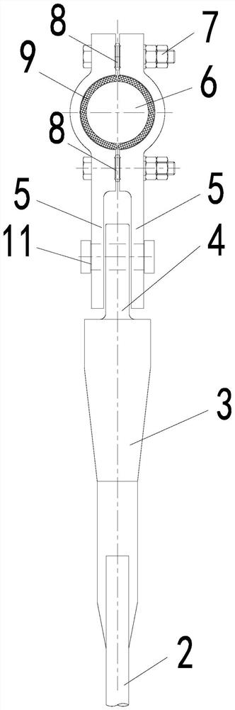
like Figure 5-Figure 10 As shown, the present embodiment provides a construction process for connecting the cable clamp of a suspension bridge to the main cable 1, including the following steps:

Step 1: Make PE stripping length marks and splint 5 length marks on the position of the cable clip on the PE surface of the main cable 1, then cut and peel off the PE on the surface of the main cable 1 according to the PE stripping length marks. The steel wire of the main cable 1 is exposed, and the dimension of the main cable surface 6 along the length direction of the main cable 1 after stripping the PE is equal to the dimension of the inner arc surface of the zinc gasket 9 along the length direction of the main cable 1;

Step 2: Buckle two pieces of zinc washers 9 into the main cable surface 6 after peeling off PE, so that the main cable surface 6 after stripping PE is in contact with the inner arc surface of the zinc washers 9;

Step 3: Align the two splints 5 and the correspondi...

Embodiment 3

In this embodiment, the main cable 1 is a finished cable with PE sheath, and its diameter is 143 mm; the main cable 1 after stripping PE is made of parallel galvanized steel wire, and its diameter is 121 mm;

Among them, the sling (rod) 2 is made of finished rigging, the anchor head 3 is in the form of a cold-cast anchor, the upper end is a single ear plate 4, and its thickness is 44mm; , The width of the mouth is 47mm to adapt to the thickness of the lug plate 4, and holes are opened on the plate for on-site installation with the pin 11 to connect with the lug plate 4.

[0040] The length of the two splints 5 is 340mm, the gap between the two splints 5 is 6mm, and the diameter of the inner arc surface of the accommodating cavity is 143mm to adapt to the diameter of the main cable 1; each splint 5 is on both sides of the main cable 1, A total of 8 bolt holes in 2 rows and 4 columns are symmetrically arranged to install the bolt connection pair. The specification is M20 high-str...


PUM


Abstract

The invention relates to a connecting structure of a suspension bridge cable clamp and a main cable and a construction technology. The cable comprises a main cable, a sling, an anchor head and a lug plate, the sling and the lug plate are connected to the two ends of the anchor head respectively, the main cable is a finished cable with a PE sheath, the cable further comprises a zinc gasket and two connected clamping plates, the clamping plates are rotationally connected to the lug plate, each clamping plate comprises a containing cavity with the cross section being in a semicircular arc shape, and the containing cavities are arranged in the containing cavities. The cross section of the zinc gasket is of a semi-arc structure, the outer arc face of the zinc gasket is attached to the inner arc face of the containing cavity, the main cable comprises the surface of the main cable after PE is stripped, and the surface of the main cable after PE is stripped is attached to the inner arc face of the zinc gasket. By arranging the zinc gasket, the defects that PE is directly clamped by the cable clamp, and the tensile strength of the PE material is limited are overcome, and large anti-sliding force can be provided by utilizing friction force between the clamping plate and the zinc gasket and friction force between the zinc gasket and the parallel galvanized steel wires in the main cable, so that the vertical bearing capacity of the sling is fully exerted.

Description

technical field [0001] The invention relates to the technical field of suspension bridges, in particular to a connection structure and construction technology of a cable clamp of a suspension bridge and a main cable. Background technique [0002] In the suspension bridge structure, the main cable is generally formed by parallel steel wire braided cables. For small and medium-span suspension bridges, the finished cable with PE (polyethylene) sheath can be used as the main cable to improve the construction convenience, durability and maintenance-free of the main cable. At this time, the boom or sling directly clamps the PE surface through the cable clamp and hangs from the main cable. When the longitudinal slope angle of the main cable is large, and the force value of the boom or sling is large, the sliding component force of the cable clip is large. There is a possibility of the sheath being pulled apart, causing the cable clip to slip. Therefore, the cable clamp method th...

Claims


Application Information

Patent Timeline
Patent Type & Authority Applications(China)
IPC IPC(8): E01D19/16E01D11/02E01D21/00
CPCE01D19/16E01D11/02E01D21/00
Inventor 朱怡
Owner WUXI MUNICIPAL DESIGN INST
Why Eureka
Try Eureka