Fabricated flexible damping spiral anchor foundation and power transmission tower

A kind of screw anchor and prefabricated technology, which is used in infrastructure engineering, protection devices, sheet pile walls, etc., can solve the problems that horizontal force cannot be ignored and the bearing capacity of screw anchor foundation cannot be fully exerted, so as to shorten the construction period on site and save energy. Construction time and cost, the effect of high vertical bearing capacity

Pending Publication Date: 2022-02-18
POWERCHINA SEPCO1 ELECTRIC POWER CONSTR CO LTD
View PDF3 Cites 0 Cited by
  • Summary
  • Abstract
  • Description
  • Claims
  • Application Information

AI Technical Summary

Problems solved by technology

The horizontal force borne by the spiral anchor part cannot be ignored. At this ti

Method used


Image

  • Fabricated flexible damping spiral anchor foundation and power transmission tower
  • Fabricated flexible damping spiral anchor foundation and power transmission tower
  • Fabricated flexible damping spiral anchor foundation and power transmission tower

Examples


Embodiment 1

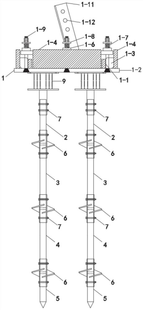
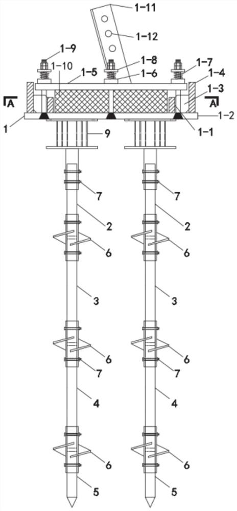
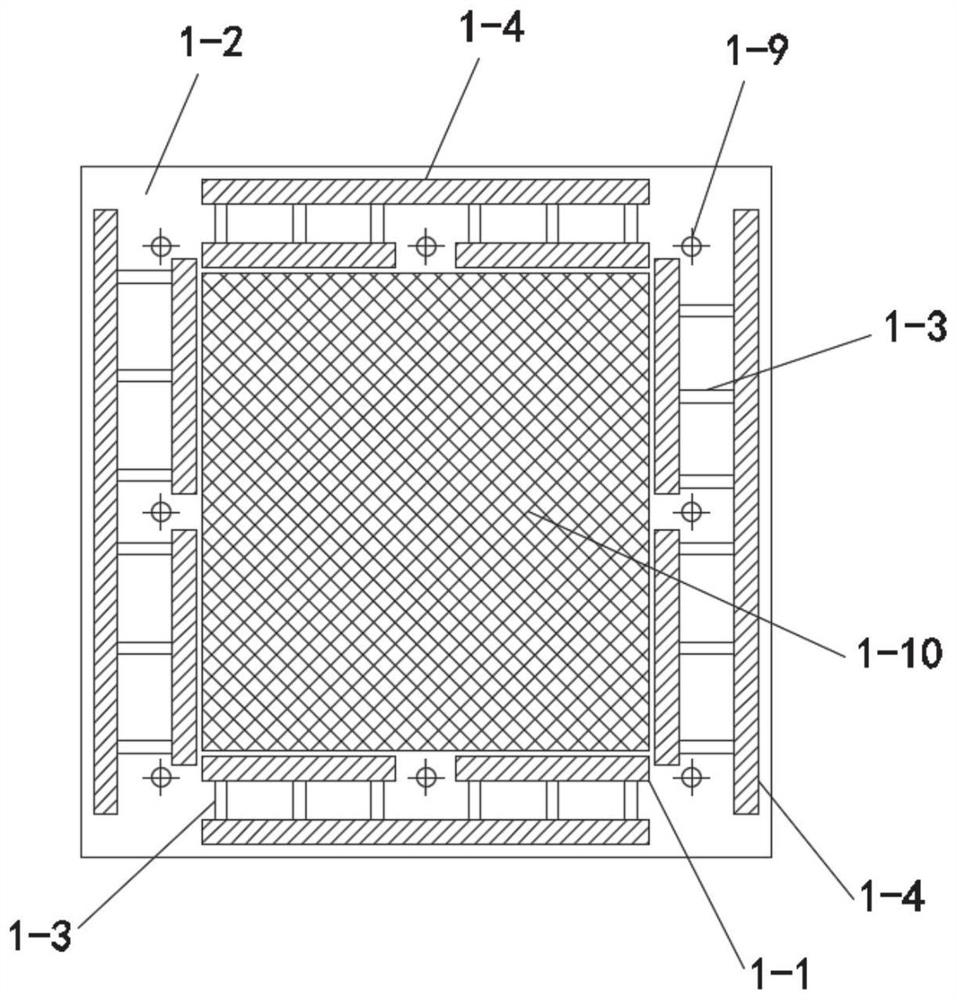
[0034] This embodiment provides an assembled flexible shock-absorbing screw anchor foundation, such as figure 1 and figure 2 As shown, it includes a shock absorbing platform 1, a flexible connecting section 9, a spiral anchor group, a blocking block, and an elastic pad 1-10. There are multiple spiral anchor groups at the bottom of the shock absorbing platform 1, and each spiral anchor group is connected through a flexible connection. The section 9 is connected with the shock absorbing platform 1, and the flexible connection between the spiral anchor group and the shock absorbing platform 1 is realized through the flexible connecting section 9, so as to reduce the horizontal force borne by the anchor rod.

[0035] Further, as shown in Figure 5(a), the flexible connecting section 9 includes a first connecting plate 9-1, a second connecting plate 9-2, a flexible pipe 9-3 and a connecting head 9-5, and the flexible pipe 9-3 One end is fixed with the first connecting plate 9-1, a...

Embodiment 2

[0062] This embodiment provides an assembled flexible shock-absorbing spiral anchor foundation. The flexible shock-absorbing spiral anchor foundation adopts the structure described in Embodiment 1, and a connecting piece 1-11 is installed on one side of the cap top plate 1-5, and through the connection The piece 1-11 is connected with the upper structure; multiple mounting holes 1-12 are opened on the connecting piece 1-11 to form multiple fixing points.

[0063] In this embodiment, the connecting piece 1-11 is an angle steel connecting piece, and the angle steel connecting piece is welded together with the platform top plate 1-5.

Embodiment 3

[0065] This embodiment provides an assembled flexible shock-absorbing spiral anchor foundation, which is different from Embodiment 1 in that prestressed steel bars are set in the spiral anchor plate 6 to further enhance the strength and rigidity of the spiral anchor plate 6. Other structures and embodiments One is the same and will not be repeated here.


PUM


Abstract

The invention discloses an assembly type flexible damping spiral anchor foundation and a power transmission tower and belongs to the technical field of power transmission line engineering. The assembly type flexible damping spiral anchor foundation comprises a damping bearing platform and a plurality of spiral anchor sets, wherein each spiral anchor set comprises a plurality of anchor rod sections, and the adjacent anchor rod sections are connected through spiral anchor discs; the flexible connecting section is installed between the top of the first anchor rod section and the damping bearing platform to form flexible connection, and the horizontal force borne by the anchor rod is reduced. The damping bearing platform and the spiral anchor set are connected together through the flexible connecting section, and the horizontal force borne by the anchor rod can be reduced; and the damping bearing platform is matched with the flexible connecting section to achieve the effects of damping and energy consumption.

Description

technical field [0001] The invention relates to the technical field of power transmission line engineering, in particular to an assembled flexible shock-absorbing spiral anchor foundation and a power transmission tower. Background technique [0002] The foundation force of the transmission tower includes vertical force and horizontal force, and the horizontal force generally accounts for 10% to 25% of the vertical force. The transmission tower is subjected to wind load all the year round, and the wind load is a kind of dynamic load. Under the action of wind load, the transmission tower is prone to shaking, which causes the bottom foundation to bear a large horizontal force. [0003] The cap and the spiral anchor of the existing spiral anchor foundation are usually welded (hardly connected), and the shaking of the transmission tower may easily cause the joint between the cap and the spiral anchor to break, resulting in extensive damage to the concrete part of the cap. Moreov...

Claims


Application Information

Patent Timeline
IPC IPC(8): E02D27/14E02D27/42E02D5/54E02D5/56E02D5/48E02D31/08
CPCE02D27/14E02D27/42E02D5/54E02D5/56E02D5/48E02D31/08E02D2600/30E02D2600/20E02D2200/1671E02D2300/0029Y02E10/72
Inventor 孟克赵戈邵国栋陈小军宋克英
Owner POWERCHINA SEPCO1 ELECTRIC POWER CONSTR CO LTD
Why Eureka
Try Eureka