Rocker arm mechanism

A technology of rocker mechanism and rocker body, which is applied in the direction of mechanical equipment, combustion engine, engine control, etc. It can solve the problems of not being able to use the engine, not being able to stop the engine cylinder and braking, and difficult to calibrate, so as to achieve the lock pin stroke Effect

Pending Publication Date: 2022-06-03
DALIAN UNIV OF TECH
View PDF6 Cites 1 Cited by
  • Summary
  • Abstract
  • Description
  • Claims
  • Application Information

AI Technical Summary

Problems solved by technology

Neither VVT nor CVVL can achieve functions such as engine deactivation and braking
Due to the large difference in the phase adjustment requirements of the intake and exhaust valves, VVT cannot be used for engines with coaxial intake and exhaust cams
VVL is difficult to use on bottom camshaft engines due to space arrangement issues
The traditional mechanical CVVL needs to be used with VVT, so it cannot be used for engines with coaxial intake and exhaust cams
Master-slave piston CVVL has problems such as poor valve operation consistency and extremely difficult calibration

Method used


Image

  • Rocker arm mechanism
  • Rocker arm mechanism
  • Rocker arm mechanism

Examples


Embodiment 1

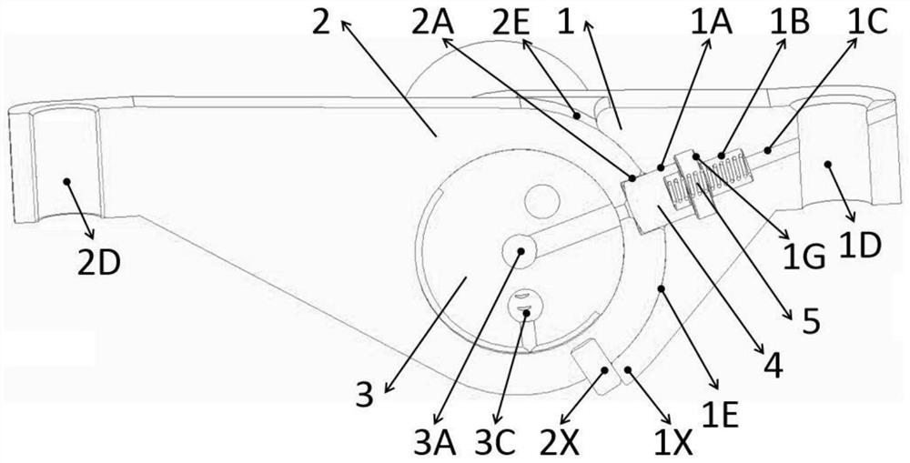
[0059] The rocker arm mechanism includes a first rocker arm body 1, a second rocker arm body 2, a rocker arm shaft 3, and a locking assembly;

[0060] The first rocker body 1 is provided with a first lock pin hole 1A, a spring hole, an emptying hole 1C, a first transmission end 1D, a first mating surface 1E, a first installation hole 1F, and a first rocker body switching limit surface 1X;

[0061] The second rocker arm body 2 is provided with a second locking pin hole 2A, a second transmission end 2D, a second mating surface 2E, a second mounting hole 2F, and a second rocker arm body switching limit surface 2X;

[0062] A control oil passage is set on the rocker arm shaft 3;

[0063] The locking assembly at least includes a lock pin 4 and a lock pin spring 5;

[0064] The first rocker arm body 1 forms an axial hinge relationship with the rocker arm shaft 3 through the first installation hole 1F, and the first installation hole 1F and the corresponding surface of the rocker a...

Embodiment 2

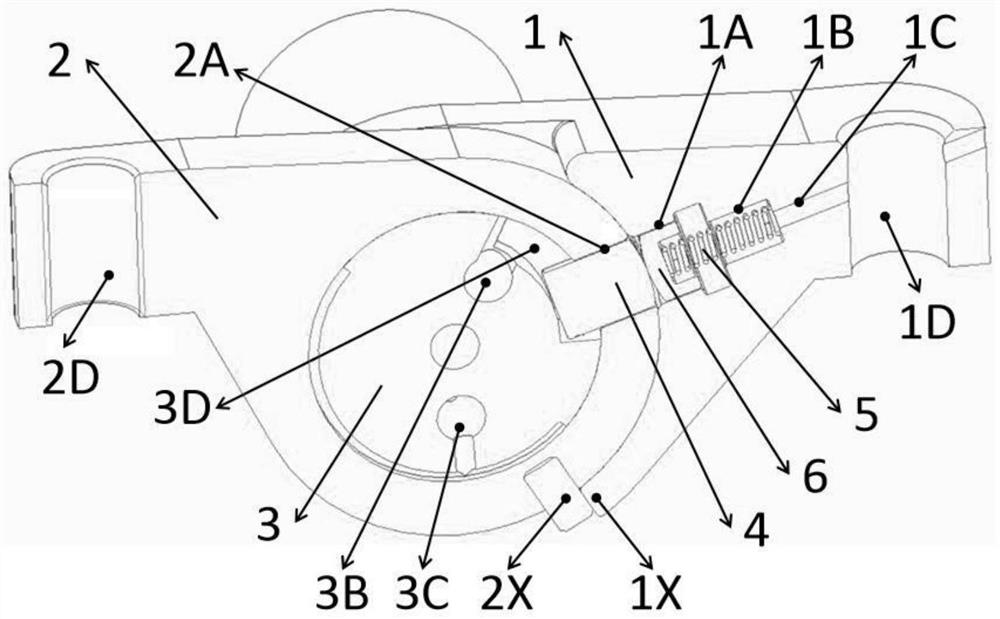
[0070] Embodiment 2 (switch type normally locked rocker arm mechanism):

[0071] Combined with the content of the above-mentioned Embodiment 1, the rocker mechanism is a normally locked rocker mechanism, the lock pin 4 is arranged in the first lock pin hole 1A, the lock pin 4 is in direct contact with the lock pin spring 5, and the lock pin 4 is in contact with the first lock pin 4. Pin hole 1A is a pair of fittings;

[0072] When the control oil passage is connected to the high pressure oil, the lock pin 4 is completely inside the first rocker arm body 1, and the first rocker arm body 1 and the second rocker arm body 2 are not locked by the lock pin 4; when the control oil passage is connected to the low pressure oil When the oil is connected, the lock pin 4 is in the first rocker arm body 1 and the second rocker arm body 2 at the same time, and the first rocker arm body 1 and the second rocker arm body 2 are locked by the lock pin 4;

[0073] In other preferred embodiments,...

Embodiment 3

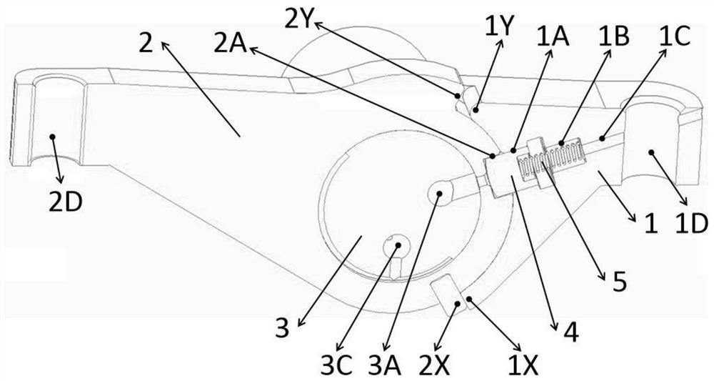
[0077] Embodiment 3 (half-switch type normally locked rocker arm mechanism):

[0078] The difference from the above-mentioned Embodiment 2 is that the first rocker arm body 1 is added with a first rocker arm body working limit surface 1Y, and the second rocker arm body 2 is added with a second rocker arm body working limit surface 2Y; When the first rocker body 1 and the second rocker body 2 are not locked by the lock pin 4, the first rocker body working limit surface 1Y and the second rocker body working limit surface 2Y restrict the first rocker body 1 and the second rocker body The relative swing amount of the two rocker arm bodies 2 .

[0079] Specifically, the working principle is as follows: For the semi-switch type normally locked rocker arm mechanism, when the control oil passage is connected to the high-pressure oil, the lock pin completely enters the first rocker arm body, and when the first rocker arm body and the second rocker arm body are on the Before the workin...


PUM


Abstract

The invention discloses a rocker arm mechanism, which relates to the technical field of engines and comprises a first rocker arm body, a second rocker arm body, a rocker arm shaft and a locking assembly, the locking assembly comprises a lock pin and a lock pin spring; a control oil duct is arranged on the rocker arm shaft and used for controlling the compression state of the lock pin spring; the two rocker arm bodies are rotatably arranged on the rocker arm shaft through respective mounting holes; the lock pin spring is arranged in the spring hole; the spring hole is communicated with the outside through the emptying hole; when the switching limiting surfaces of the two rocker arm bodies are in contact, the relative positions of the two rocker arm bodies are switchable positions, the two lock pin holes are aligned and form a locking channel, and the lock pin can move in the locking channel; when the switching limiting faces of the two rocker arm bodies are not in contact, the relative positions of the two rocker arm bodies are non-switchable positions, the two lock pin holes are not aligned, a locking channel cannot be formed, and the lock pins can only be completely located in the corresponding lock pin holes. Through the arrangement, the variable rocker arm mechanism is provided.

Description

technical field [0001] The present invention relates to the technical field of engines, in particular to an engine rocker arm. Background technique [0002] The increasingly serious energy and environmental problems have become a major global problem. The use of technologies including cylinder deactivation and internal EGR can effectively improve engine performance, which is of great significance in terms of energy conservation and emission reduction. The engine cylinder deactivation technology can improve fuel economy and exhaust temperature by stopping the work of some cylinders under low load in the driving mode and increasing the load rate of the working cylinders. In the engine start-up and warm-up phase, the use of internal EGR technology can speed up the increase of in-cylinder and exhaust gas temperatures, improve engine combustion efficiency and stability, and shorten the time required for the aftertreatment device to start working, thereby achieving engine energy s...

Claims


Application Information

Patent Timeline
Patent Type & Authority Applications(China)
IPC IPC(8): F01L1/18F01L1/46F02D13/06
CPCF01L1/183F01L1/46F02D13/06Y02T10/12
Inventor 崔靖晨隆武强田华
Owner DALIAN UNIV OF TECH
Why Eureka
Try Eureka