Oil film sealing structure of valve

An oil film sealing and valve technology, applied in flange connection, passing components, mechanical equipment, etc., can solve the problems of difficult installation and disassembly of oil film sealing structure, affecting the convenient use of oil film sealing structure, and loosening of oil film sealing structure connection, etc. Increase the function of fixed socket, increase the fixed function, increase the effect of fixedness

Pending Publication Date: 2022-06-03
慎晓霞
View PDF0 Cites 0 Cited by
  • Summary
  • Abstract
  • Description
  • Claims
  • Application Information

AI Technical Summary

Problems solved by technology

[0005] The invention provides an oil film sealing structure of a valve, one of which is to have the function of increasing the solidity, so as to solve the problem that when the oil film sealing structure of the valve is in use, due to its poor fixity, the oil film is easily caused by the impact of the water flow. The connection of the oil film seal structure is loose, which affects the tightness of the structure; another purpose is to solve the difficulty in the installation and disassembly of the oil film seal structure of the valve, which leads to slow maintenance and replacement of the oil film seal structure in the later stage, affecting the oil film seal The problem of convenient use of the structure, in order to achieve the effect of convenient disassembly and installation

Method used


Image

  • Oil film sealing structure of valve
  • Oil film sealing structure of valve
  • Oil film sealing structure of valve

Examples


Embodiment 1

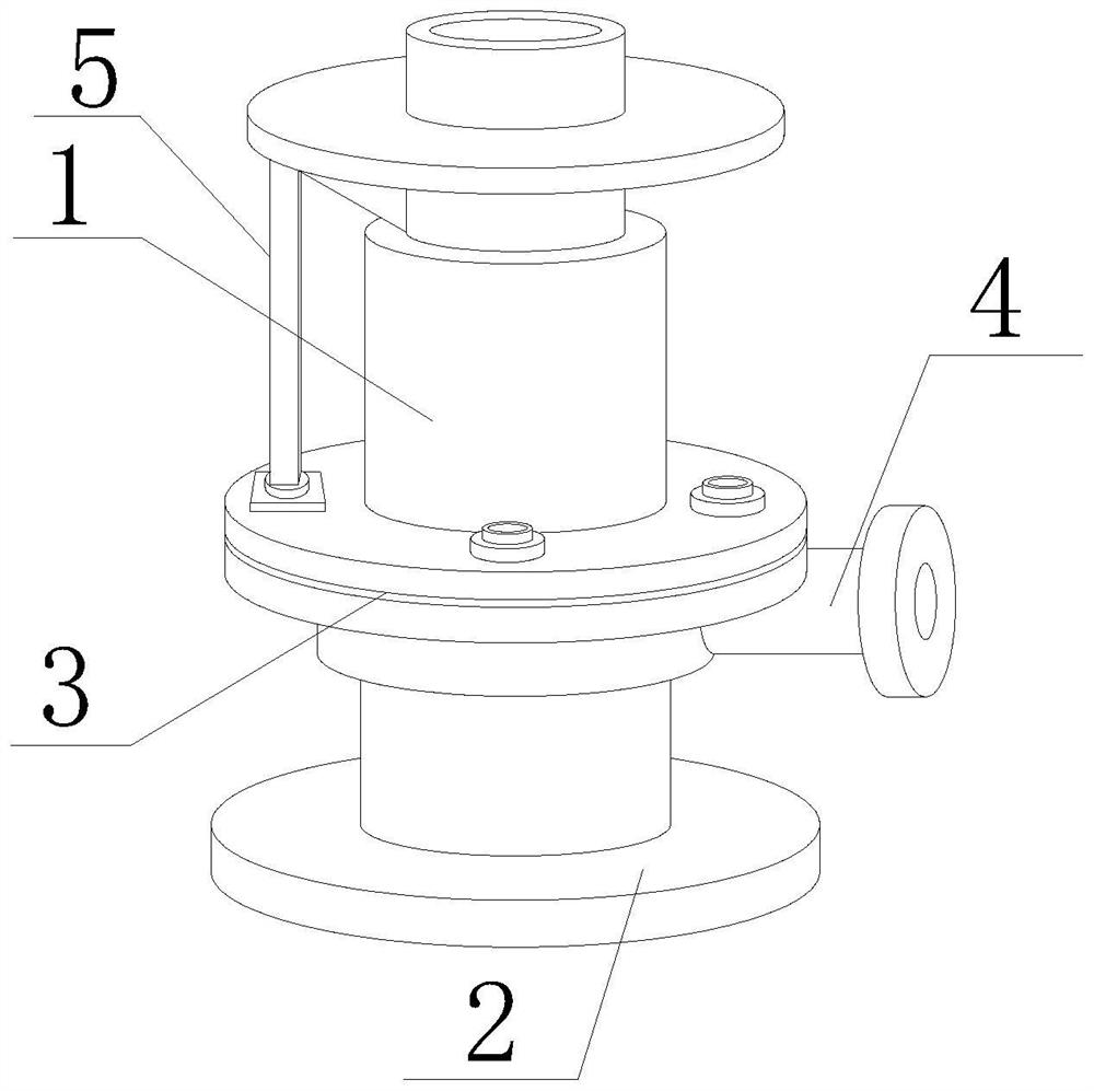
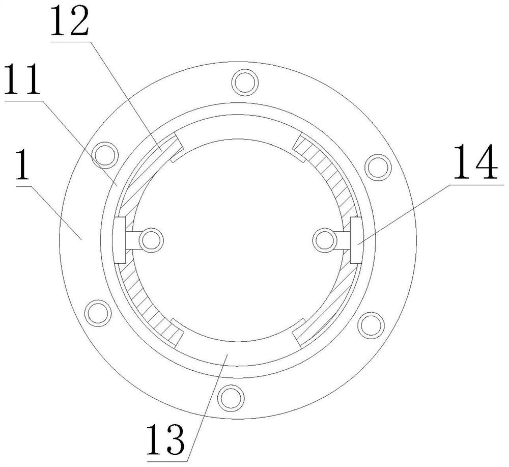
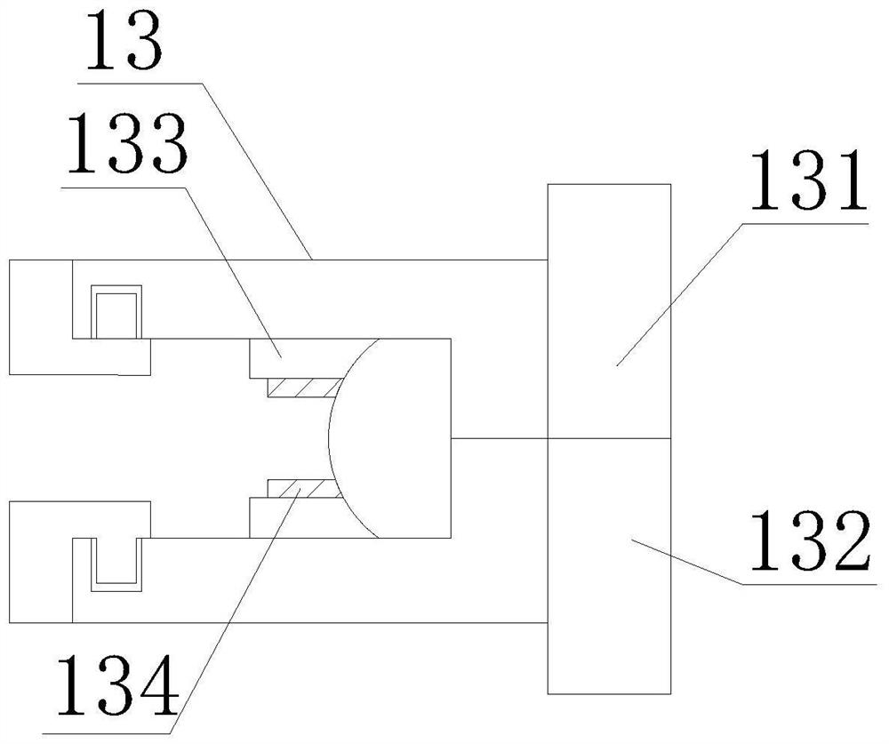
[0044] like Figure 1-8 As shown, the present invention provides an oil film sealing structure for a valve, including a valve body 1, a connecting base 2, a sealing flange 3 and a connecting pipe 4, the bottom of the valve body 1 is fixedly installed with the connecting base 2, and the middle part of the valve body 1 A sealing flange 3 is provided, a connecting pipe 4 is fixedly connected to one side of the bottom of the sealing flange 3, a connecting reinforcement rod 5 is fixedly installed on the top of the sealing flange 3, and a mounting block is fixedly installed inside the valve body 1. The mounting block A sealing film 12 is arranged on the outer side of the sealing film 12, a limit block 13 is arranged on the outer side of the sealing film 12, and a socket block 135 is movably installed on both sides of the limit block 13. The limit block 13 includes an upper card board 131. The plug board 1311 is fixedly installed, the bottom of the plug board 1311 is provided with a ...

Embodiment 2

[0047] like Figure 1-8 As shown, on the basis of Embodiment 1, the present invention provides a technical solution: preferably, a fixed baffle 14 is fixedly installed on the top of the sealing membrane 12, and one end of the fixed baffle 14 is fixedly installed on the inner wall of the valve body 1 , the bottom of the fixed baffle 14 is provided with a moving slot 141, the interior of the moving slot 141 is provided with a telescopic column 142, the other end of the telescopic column 142 is fixedly installed with a moving block 143, and the bottom of the moving block 143 is fixedly installed with a pressing block 144, the pressing block A friction pad is fixedly installed on the side of 144 close to the inner wall of the valve body 1 .

[0048] In this embodiment, when the sealing film 12 cooperates with the limiting block 13 to be fixedly installed, the telescopic column 142 is telescopically moved to drive the moving block 143 to move inside the moving groove 141 , so that ...

Embodiment 3

[0050] like Figure 1-8 As shown, on the basis of Embodiment 1, the present invention provides a technical solution: preferably, the top of the fixed plate 14 is provided with a fixed pressure ring 11, and the outer side of the fixed pressure ring 11 is fixedly installed on the inner wall of the valve body 1, The bottom of the fixed pressure ring 11 is provided with a lifting rod 111, the bottom of the lifting rod 111 is provided with a mounting ring 112, the bottom of the mounting ring 112 is fixedly mounted with a squeeze pad 113, and the inside of the squeeze pad 113 is fixedly mounted with a buffer pressure pad 1131, A rubber pad 1132 is fixedly installed at the bottom of the buffer pressure pad 1131 , and friction particles are fixedly installed at the bottom of the rubber pad 1132 .

[0051] In this embodiment, when the sealing film 12 is sealed and fixed, it cooperates with the lifting rod 111 to telescopically move, and drives the mounting ring 112 to move and squeeze ...


PUM


Abstract

The invention discloses an oil film sealing structure of a valve, and relates to the technical field of sealing structures, the oil film sealing structure comprises a valve main body, a connecting base, a sealing flange and a connecting pipe, the bottom of the valve main body is fixedly provided with the connecting base, the middle of the valve main body is provided with the sealing flange, and one side of the bottom of the sealing flange is fixedly connected with the connecting pipe. Through movement of the sleeving block towards the two sides, the sleeving block drives the sleeving clamping block to be separated from the limiting groove, the clamping separation effect is achieved, accordingly, the upper clamping plate and the lower clamping plate are conveniently and vertically separated, the limiting block is conveniently disassembled, then the telescopic rod telescopically moves to push the clamping block to eject out of the inner wall, separated from the sealing film, of the valve main body, and the sealing film is separated from the valve main body. And the problem that the oil film sealing structure of the valve is difficult to mount and dismount, so that the later maintenance and replacement of the oil film sealing structure are slow is solved, the device is convenient to dismount, the convenience of the device is improved, and the later maintenance of the device is facilitated.

Description

technical field [0001] The invention relates to the technical field of sealing structures, in particular to an oil film sealing structure of a valve. Background technique [0002] The valve is a control component in the fluid conveying system, with functions such as cut-off, regulation, diversion, diversion, and pressure relief. Valves are widely used in the fields of petroleum, natural gas, mining, petrochemical, electric power and smelting production. The valve structure in the prior art usually includes a valve body. The valve body is provided with a fluid channel, and the fluid channel is provided with a blocking or conducting fluid. On-off valve core structure, the valve core structure is connected with the operating mechanism through the valve shaft, and the valve core structure is opened or closed by driving the operating mechanism, and there is a sealing structure between the surface of the valve core structure and the inner wall of the fluid channel, and the sealing...

Claims


Application Information

Patent Timeline
IPC IPC(8): F16L23/16
CPCF16L23/16
Inventor 慎晓霞
Owner 慎晓霞
Why Eureka
Try Eureka