
Dust collecting device

A collection device and dust technology, which is applied in the direction of sampling device, measuring device, combined device, etc., can solve the problems of less dust collection, sandstorm hazards, and short observation time, so as to improve collection efficiency, ensure air flow rate, and improve The effect of collection volume

Pending Publication Date: 2022-06-03
XINJIANG INST OF ECOLOGY & GEOGRAPHY CHINESE ACAD OF SCI
View PDF0 Cites 2 Cited by
  • Summary
  • Abstract
  • Description
  • Claims
  • Application Information

AI Technical Summary

Problems solved by technology

[0002] Sandstorms have great harm to nature, especially the impact on the environment and human health. Researchers from all over the world engaged in sandstorm control are working day and night, fighting on the front line of sandstorm control. A lot of manpower and material resources have been invested in the research and management of hazards, hazards, and obvious results have been achieved. However, with the deteriorating climate and environment, the hazards of sandstorms are becoming more and more serious. Therefore, the research on sandstorms must be strengthened and strong strong measures
[0003] In the actual working environment, in order to study the control measures of wind and sand, experts in wind and sand control usually use sand accumulators to collect sand and dust particles in the airflow, and conduct research on the number and particle size of the collected sand and dust particles, but now In the process of collecting fine dust particles on the surface of sandstorms, some sand accumulation instruments have the defects of small amount of dust collected and short observation time, which makes it impossible to test the physical and chemical properties of the collected dust particles such as salt content and particle size, which in turn affects the quality of the sand dust collected. Study on the Control of Wind and Sand

Method used


Image

  • Dust collecting device
  • Dust collecting device
  • Dust collecting device

Examples


Embodiment Construction

[0030] The technical solutions in the embodiments of the present invention will be clearly and completely described below with reference to the accompanying drawings in the embodiments of the present invention. Obviously, the described embodiments are only a part of the embodiments of the present invention, rather than all the embodiments. Based on the embodiments of the present invention, all other embodiments obtained by those of ordinary skill in the art without creative efforts shall fall within the protection scope of the present invention.

[0031] In order to make the above objects, features and advantages of the present invention more clearly understood, the present invention will be described in further detail below with reference to the accompanying drawings and specific embodiments.

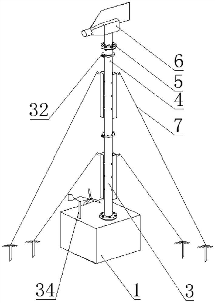
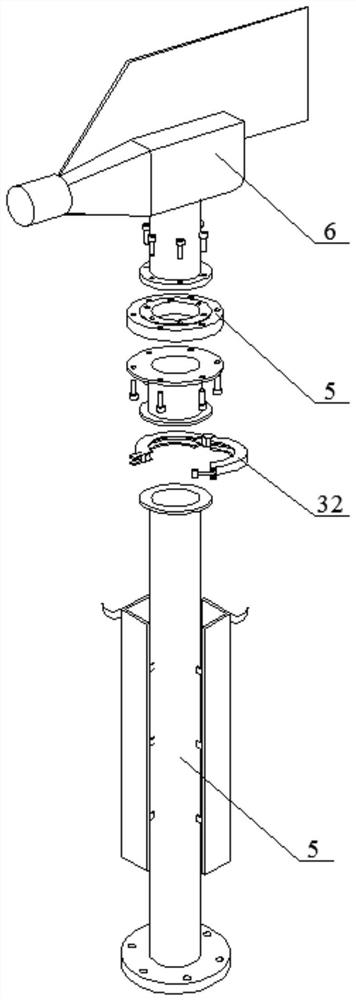
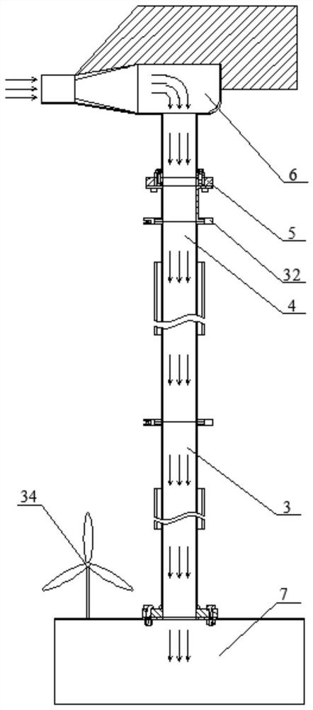
[0032] refer to Figure 1-6 , Embodiment 1: The present invention provides a sand and dust collection device, including a collection box 1, the top of the collection box 1 is provided ...


PUM


Abstract

The invention discloses a sand and dust collecting device which comprises a collecting box, an air channel opening is formed in the top end of the collecting box, a lower ventilation pipe is arranged at the top end of the collecting box, the bottom end of the lower ventilation pipe communicates with the air channel opening, an upper ventilation pipe is detachably connected to the top end of the lower ventilation pipe, and a bearing is arranged at the top end of the upper ventilation pipe; the upper ventilation pipe and the lower ventilation pipe are each provided with a fixing pull wire, a settling chamber is arranged in the collecting box, an air duct opening corresponds to the settling chamber, and a sand and dust collecting mechanism is arranged in the collecting box and corresponds to the settling chamber. According to the invention, sand and dust data of more than PM2.5 can be collected, the blank that the existing sand collecting equipment can collect sand and cannot collect dust in the sand storm earth surface process is filled up, the defects of less sand and dust collection amount, short observation time and the like of TSP can be made up, and the sand and dust collection efficiency is improved.

Description

technical field [0001] The present invention relates to the technical field of collection devices, in particular to a sand and dust collection device. Background technique [0002] Sandstorms have great harm to nature, especially the impact on the environment and the harm to human health. Scientific researchers engaged in sandstorm control from all over the world are working day and night, fighting on the front line of sandstorm control. A lot of manpower and material resources have been invested in the research and management of hazards, and obvious results have been achieved. However, with the deteriorating climate and environment, the hazards of sandstorm formation are becoming more and more serious. Therefore, the research on sandstorms must be strengthened. strong measures. [0003] In the real working environment, in order to study the control measures of wind sand, sand control experts usually use a sand accumulator to collect sand and dust particles in the airflow, ...

Claims


Application Information

Patent Timeline
Patent Type & Authority Applications(China)
IPC IPC(8): G01N1/22G01N1/24B01D50/20
CPCG01N1/22G01N1/2205G01N1/2273G01N1/24G01N2001/241Y02A50/2351
Inventor 俞祥祥范敬龙王海峰靳正忠丁刚李芳国
Owner XINJIANG INST OF ECOLOGY & GEOGRAPHY CHINESE ACAD OF SCI
Learn More