Oil pumping condition fusion reasoning identification method based on indicator diagram fusion similarity

A recognition method and a technology of dynamometer diagrams, which are applied in the field of oil well production and pumping, can solve problems such as insufficient similarity stability and changes in image hash values, and achieve the effects of improving recognition accuracy, recognition sensitivity, and improving recognition rate

Pending Publication Date: 2022-06-03
南京富岛油气智控科技有限公司
View PDF0 Cites 1 Cited by
  • Summary
  • Abstract
  • Description
  • Claims
  • Application Information

AI Technical Summary

Problems solved by technology

However, the local sensitive hash algorithm is very sensitive to the content of the picture due to its strong local analysis ability, and small content interference can easily cause a large change in the hash value of the picture, resulting in insufficient stability of the overall similarity evaluation.
[0007] The similarity obtained based on the Pearson correlation coefficient algorithm and the local hash algorithm is fused according to certain steps, and the advantages of the two are fully utilized to obtain a more reasonable similarity between the image to be tested and the sample image, and finally effectively improve the recognition rate. , this method has not been publicly reported

Method used


Image

  • Oil pumping condition fusion reasoning identification method based on indicator diagram fusion similarity
  • Oil pumping condition fusion reasoning identification method based on indicator diagram fusion similarity
  • Oil pumping condition fusion reasoning identification method based on indicator diagram fusion similarity

Examples


example 1

[0194] The similarity of each working condition picture is used as the probability assignment of this picture to this working condition. Since the working condition of the picture has been calibrated, the probability assignment of the remaining working conditions of this picture must be 0.

[0195] for example:

[0196] Example 1: The first picture is working condition A 1 , the fusion similarity between the difficult image to be tested and the first image is P 1 (A 1 ), then the basic probability assignment (BPA) of the evidence for the ith matching picture is expressed as the first picture for case A 1 The probability assignment m of 1 (A 1 ) is P 1 (A 1 ), assign the probability of other working conditions to 0, denoted as The form is shown in Table 3.

example 2

[0197] table 3 Tabular form

[0198]

[0199] Example 2: There are five pictures after the secondary screening, the first picture is the same as the working condition A 1 The similarity is P 1 (A 1 ), the second picture is with case A 2 The similarity is P 2 (A 2 ), the third picture and condition A 1 The similarity is P 3 (A 1 ), the fourth picture and condition A 2 The similarity is P 4 (A 2 ), the fifth picture and condition A 3 The similarity is P 5 (A 3 ). Then the basic probability assignment (BPA) of the five matching graph evidences are expressed as

[0200]

[0201]

[0202] The form is shown in Table 4.

[0203] Table 4 the form of

[0204]

[0205] (4-8-3) Fusion of n pieces of evidence

[0206] Perform evidence fusion on the Basic Probability Assignment (BPA) of n graphs, and obtain the comprehensive probability assignment value m(A) of each working condition after fusion. j ), which are ag...


PUM


Abstract

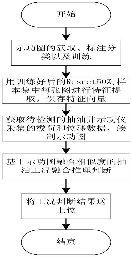
The invention discloses an oil pumping condition fusion reasoning identification method based on indicator diagram fusion similarity. The method comprises the following steps: (1) indicator diagram acquisition, labeling classification and training; (2) performing feature extraction on each image in the sample set by using the trained Resnet50, and storing a feature vector; (3) acquiring load and displacement data acquired by a pumping well indicator to be detected, and drawing an indicator diagram; (4) oil pumping condition fusion reasoning judgment based on indicator diagram fusion similarity; and (5) sending a working condition judgment result to an upper position for display. A fusion similarity calculation method is provided. The similarity obtained based on the Pearson's correlation coefficient algorithm and the local Hash algorithm is fused according to certain steps, the advantages of the Pearson's correlation coefficient algorithm and the local Hash algorithm are brought into full play, the more reasonable similarity between the to-be-detected image and the sample image is obtained, and finally the recognition rate is effectively improved.

Description

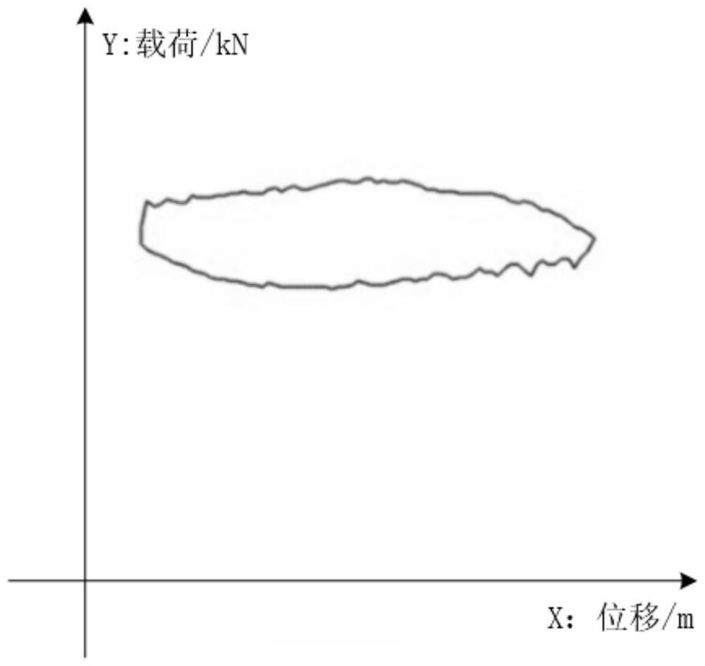
technical field [0001] The invention relates to the fields of oil production and oil pumping in oil wells, in particular to a method for fusion reasoning and identification of oil pumping conditions based on the fusion similarity of dynamometer diagrams. Background technique [0002] The oil pumping dynamometer chart is the main means to understand the working conditions of the pipes, rods and pumps in the well. Analysis and interpretation of the dynamometer diagram is a main means to directly understand the working condition of the deep well pump. All abnormal phenomena in the operation of the deep well pump can be reflected more intuitively on the dynamometer diagram. [0003] The pumping unit is the core equipment in the oil extraction process. It is only manpower to judge the working condition of the pumping unit and operate the operation of the pumping unit, which is inefficient and cannot meet the needs of the development of the industry. [0004] Under the background...

Claims


Application Information

Patent Timeline
IPC IPC(8): G06V10/74G06V10/80G06V10/764G06V10/82G06K9/62G06N3/08
CPCG06N3/08G06F18/22G06F18/24G06F18/25
Inventor 叶彦斐刘帅沈濮均姜磊史永翔涂娟
Owner 南京富岛油气智控科技有限公司
Why Eureka
Try Eureka