A high-speed punching machine for motor iron core processing

A high-speed punching and iron core technology, applied in metal processing equipment, manufacturing motor generators, manufacturing tools, etc., can solve the problems of reducing punching efficiency, inconvenient use, complicated steps, etc. The effect of comfort

Active Publication Date: 2022-07-12
常州市昌隆电机股份有限公司
View PDF19 Cites 0 Cited by
  • Summary
  • Abstract
  • Description
  • Claims
  • Application Information

AI Technical Summary

Problems solved by technology

[0003] When the motor iron core is processed, it is necessary to manually locate the iron core one by one. The steps are complicated and inconvenient to use, which directly reduces the efficiency of punching.

Method used


Image

  • A high-speed punching machine for motor iron core processing
  • A high-speed punching machine for motor iron core processing
  • A high-speed punching machine for motor iron core processing

Examples


Embodiment 1

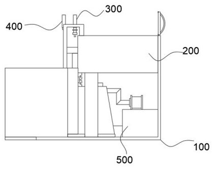
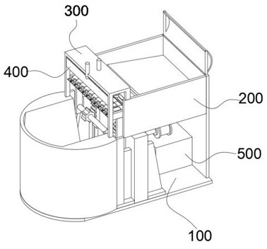
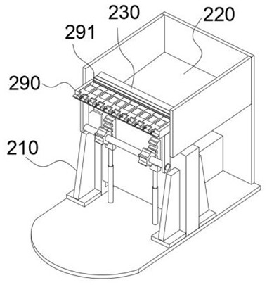
[0047] combine Figure 1-Figure 10As shown, the present invention provides a high-speed punching machine for motor iron core processing, including an L-shaped substrate 100, and the L-shaped substrate 100 is provided with a feeding module 200, a punching module 300 and a discharging module 400. The loading module 200 includes two brackets 210 connected to the top of the L-shaped substrate 100 , a U-shaped plate 220 connected between the L-shaped substrate 100 and the two brackets 210 , and the outer wall of the U-shaped plate 220 . The lifting plate 230 frictionally and slidingly connected between the two brackets 210, the two limiting plates 240 located at the bottom of the U-shaped plate 220 and connected to the inner side of the lifting plate 230, and slidingly installed on the two The rotating rod 250 between the limit plates 240 , the motor 260 whose output shaft is connected to the rotating rod 250 , the baffle plate 270 rubbing against the outer wall of the lifting plat...

Embodiment 2

[0056] combine figure 1 , figure 2 and Figure 10 As shown, on the basis of the first embodiment, the L-shaped substrate 100 is further provided with a recycling module 500, and the recycling module 500 includes a belt conveyor 510 connected to the top of the L-shaped substrate 100 and a belt conveyor 510 connected to the L-shaped substrate 100. The frame body 520 connected to the top of the shaped base plate 100, the belt conveyor 510 is located between the two cylinders 294, one end of the belt conveyor 510 extends to the inside of the frame body 520, the bottom of the motor 260 is connected to the top of the frame body 520, The recycling module 500 can collect the unprocessed parts that have slipped from the flushing box 290, and play the role of recycling the parts.

Embodiment 3

[0058] combine Figure 4 , Figure 5 and Figure 8 As shown, in the above embodiment, a metal rod is provided on the cloth tape 280, the metal rod is located at the center of the cloth tape 280, the length of the metal rod is equal to the cloth tape 280, and the metal rod is used to guide the cloth tape 280 , when the cloth belt 280 is loosened, the metal rod presses the middle of the cloth belt 280 downward to prevent the cloth belt 280 from wrinkling between the punching box 290 and the baffle 270 .

[0059] The working principle and use process of the present invention: in the initial state, a large number of iron cores to be processed are placed in the placement cavity, and then when the present invention is put into practical use, the motor 260 is started to make the rotating rod 250 rotate. The lift plate 230 will complete a lift, wherein, each time the lift plate 230 rises, it will lift up with a part of the iron core, the iron core is attached to the baffle 270, and ...


PUM


Abstract

The invention relates to the technical field of motor iron core processing, in particular to a high-speed punching machine for motor iron core processing, comprising an L-shaped base plate, and a feeding module, a punching module and a discharging module are arranged on the L-shaped base plate, and the upper The material module includes two brackets connected to the top of the L-shaped base plate. In the present invention, every time the motor drives the rotating rod to rotate once, the lifting plate will complete a lifting and lowering, and when the lifting plate rises, it will lift up with a part of the iron core, and then when the top of the lifting plate is flush with the top of the baffle, the iron core automatically slides down from On the pressure plate, here, because the iron core is transported randomly, part of the iron core cannot enter the positioning groove smoothly. To solve this situation, the movable end of the cylinder drives the tooth plate to rise and fall, and then the punching box connected to the gear rotates left and right. The iron core on the punching box that does not enter the positioning slot falls, and then the lifting plate continues to replenish the iron core into the positioning slot until all the positioning slots are filled, and the iron core positioning is mechanically completed, which is convenient to use and improves the punching efficiency.

Description

technical field [0001] The invention relates to the technical field of motor iron core processing, in particular to a high-speed punching machine for motor iron core processing. Background technique [0002] Commonly used transformer cores are generally made of silicon steel sheets. Silicon steel is a kind of steel containing silicon (silicon is also called silicon), and its silicon content is 0.8~4.8%. The iron core of the transformer is made of silicon steel because silicon steel itself is a magnetic material with strong magnetic permeability. [0003] When the motor iron core is processed, it is necessary to manually position the iron core one by one, which is complicated and inconvenient to use, which directly reduces the efficiency of punching. SUMMARY OF THE INVENTION [0004] The present invention aims to solve one of the technical problems existing in the prior art or related technologies. [0005] For this reason, the technical scheme adopted in the present inv...

Claims


Application Information

Patent Timeline
Patent Type & Authority Patents(China)
IPC IPC(8): B21D28/22B21D45/02B21D43/20B21D28/04B21D43/04H02K15/02
CPCB21D28/22B21D45/02B21D43/20B21D28/04B21D43/04H02K15/024
Inventor 高昱王建南黄丽萍王璐颖曹洲陆寒峰关正张平山
Owner 常州市昌隆电机股份有限公司
Why Eureka
Try Eureka