Garbage incinerator

A technology for waste incinerators and furnace bodies, which is applied to incinerators, combustion types, combustion methods, etc., can solve the problems of incomplete incineration of waste, unstable temperature in the furnace, and easily extinguished flames, so as to accelerate waste incineration efficiency, The effect of saving incineration cost and reducing labor pressure

Inactive Publication Date: 2022-06-07
李绍亭
View PDF0 Cites 0 Cited by
  • Summary
  • Abstract
  • Description
  • Claims
  • Application Information

AI Technical Summary

Problems solved by technology

[0005] Aiming at the deficiencies in the prior art, the present invention provides a garbage incinerator, which has the advantages of effectively preventing flames from being easily extinguished, complete garbage incineration, high incineration efficiency, and filter screens that are not easily blocked, and solves the problem of incomplete garbage incineration and easy flames. Putting out, the temperature in the furnace is unstable, and the filter screen is easy to block

Method used


Image

  • Garbage incinerator
  • Garbage incinerator
  • Garbage incinerator

Examples


Embodiment 1

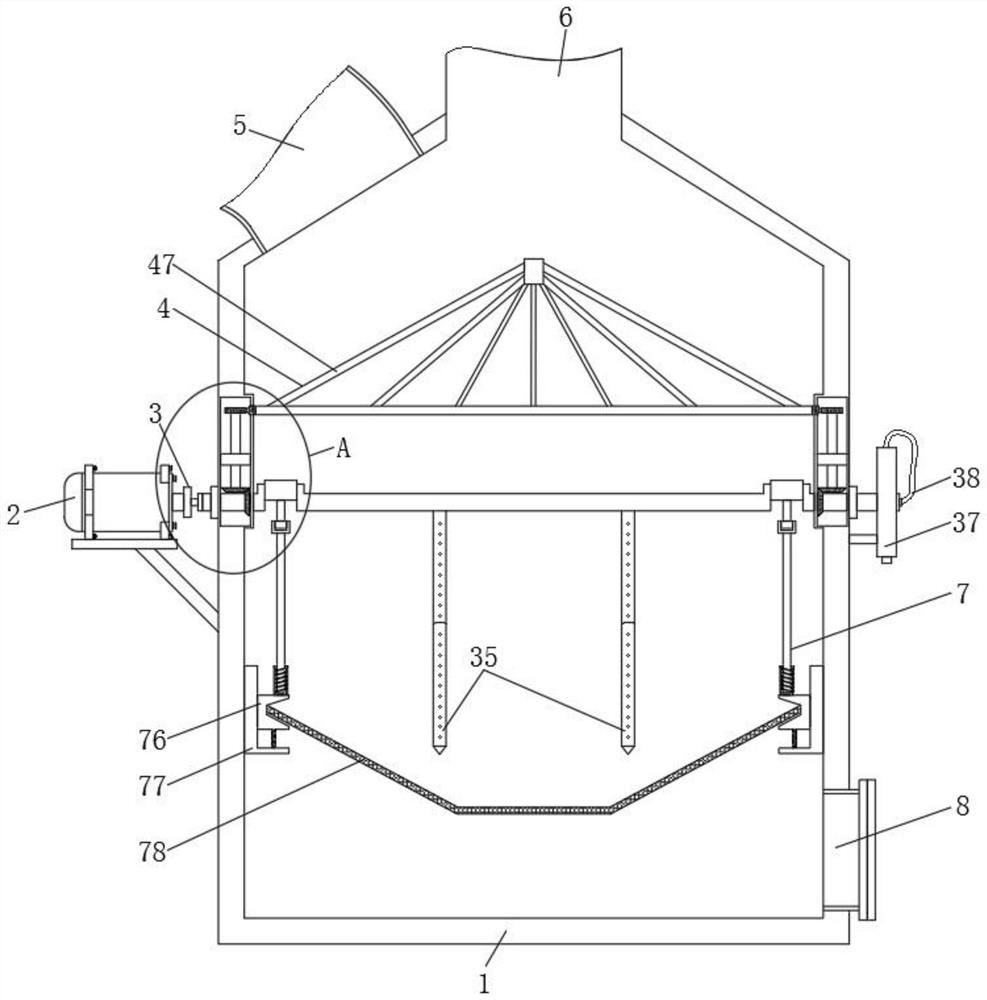
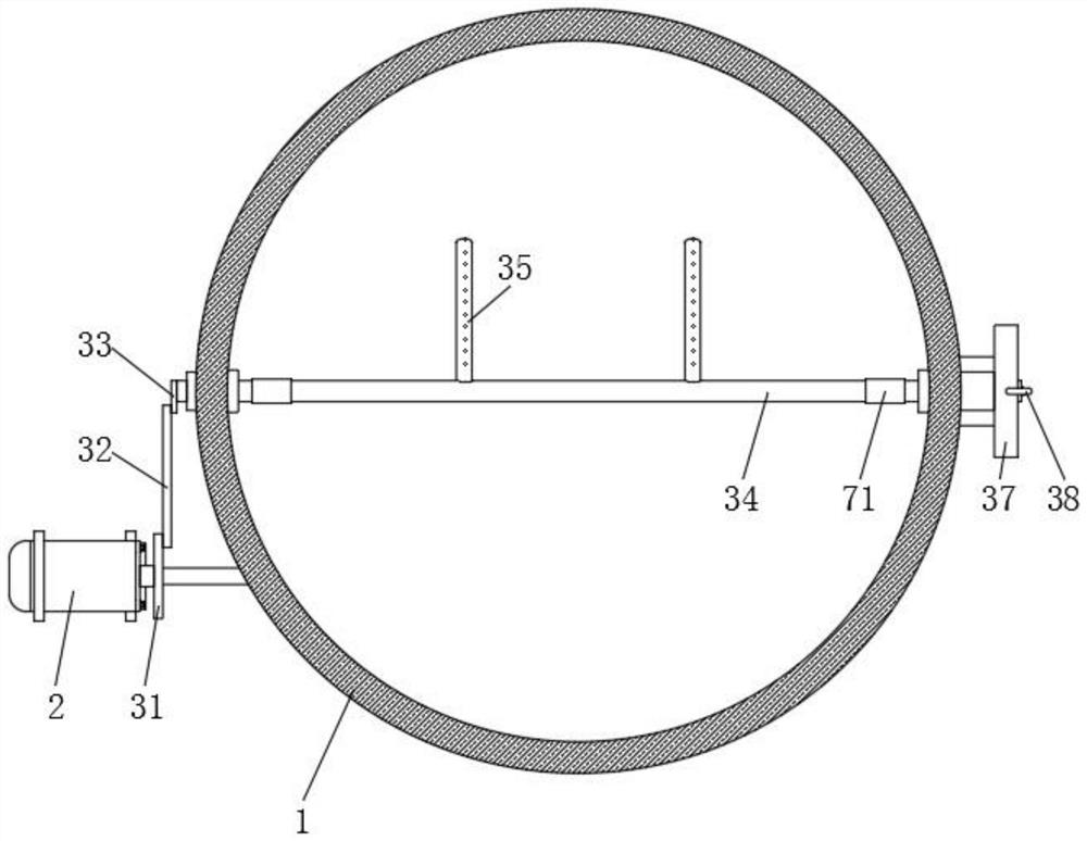
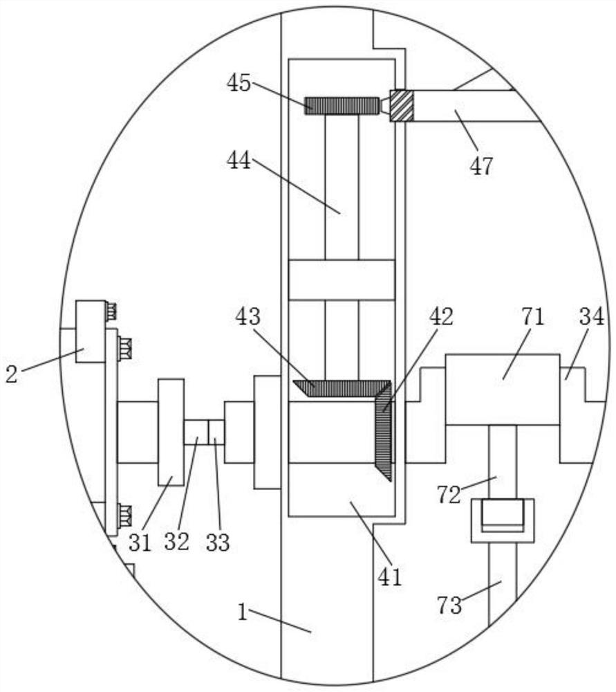
[0028] see Figure 1-3 , Figure 5-7 , a waste incinerator, comprising a furnace body 1, a motor 2 is fixedly installed in the middle position of the left side of the furnace body 1, a turning mechanism 3 is fixedly connected with the motor 2, and the turning mechanism 3 includes a turntable 31 fixedly connected with the motor 2, and the turntable 31 One side is rotatably connected with a connecting rod 32, one side of the connecting rod 32 is rotatably connected with a short rod 33, one side of the short rod 33 is fixedly connected with a rotating shaft 34, and the middle position of the rotating shaft 34 is fixedly connected with a turning rod 35, and the turning rod 35 is set as C The outer part of the right end of the rotating shaft 34 is sleeved with a fan blade 36, and the outer part of the fan blade 36 is provided with a sealing box 37, the sealing box 37 has air tightness, and the upper end of the sealing box 37 is inserted There is a trachea 38, the bottom end of the...

Embodiment 2

[0032] see Figure 1-7 , a waste incinerator, comprising a furnace body 1, a motor 2 is fixedly installed in the middle position of the left side of the furnace body 1, a turning mechanism 3 is fixedly connected with the motor 2, and the turning mechanism 3 includes a turntable 31 fixedly connected with the motor 2, and the turntable 31 One side is rotatably connected with a connecting rod 32, one side of the connecting rod 32 is rotatably connected with a short rod 33, one side of the short rod 33 is fixedly connected with a rotating shaft 34, and the middle position of the rotating shaft 34 is fixedly connected with a turning rod 35, and the turning rod 35 is set as C The outer part of the right end of the rotating shaft 34 is sleeved with a fan blade 36, and the outer part of the fan blade 36 is provided with a sealing box 37, the sealing box 37 has air tightness, and the upper end of the sealing box 37 is inserted There is a trachea 38, the bottom end of the trachea 38 is ...


PUM


Abstract

The invention relates to the technical field of garbage treatment, and discloses a garbage incinerator which comprises an incinerator body, a motor is fixedly installed at the middle section position of the left side of the incinerator body, the motor is fixedly connected with a turning mechanism, an anti-extinguishing mechanism is arranged at the upper end of the turning mechanism, and a feeding port is formed in the upper left end of the anti-extinguishing mechanism; a flue is arranged on the right side of the feeding port, a vibration mechanism is arranged on the upper side of the bottom end of the furnace body, and an ash outlet is formed in the right side of the bottom end of the vibration mechanism. According to the garbage incinerator, through the arranged turning mechanism, garbage combustion is more thorough, the combustion efficiency is higher, harmful gas is prevented from being generated due to incomplete garbage combustion, the body health of workers is prevented from being damaged, and through the arranged extinguishing prevention mechanism, the situation that the garbage directly falls to cover the combusting garbage, flames are prone to being extinguished, and the temperature in the incinerator body is unstable is effectively prevented; incineration efficiency is improved, and incineration cost is saved.

Description

technical field [0001] The invention relates to the technical field of garbage disposal, in particular to a garbage incinerator. Background technique [0002] Garbage incineration is a traditional method of disposing of garbage. After the garbage is treated by incineration, it can significantly reduce the amount of garbage and save land. At the same time, it can also eliminate various virus pathogens and convert toxic and harmful substances into harmless substances. Therefore, garbage incineration The method has become one of the main methods of municipal waste disposal. [0003] However, the existing waste incinerators often have several problems. When the existing waste incinerators are incinerated, the waste is often piled up due to the excessive amount of waste. The incineration is not complete, and the incineration efficiency is relatively low, which greatly wastes resources. When new garbage is put in, large pieces of garbage are easy to cover the incineration flame, ...

Claims


Application Information

Patent Timeline
Patent Type & Authority Applications(China)
IPC IPC(8): F23G7/00F23G5/04F23G5/44F23G5/46F23J15/02F23J1/00
CPCF23G7/00F23G5/04F23G5/44F23G5/46F23J15/025F23J1/00
Inventor 李绍亭
Owner 李绍亭
Why Eureka
Try Eureka