Sliding feeding device

A technology of sliding feeding and sliding rails, which is applied in the direction of combustion method, combustion type, incinerator, etc., and can solve the problems of single structure of throwing port and furnace door, affecting incineration efficiency, etc.

Inactive Publication Date: 2015-11-25
池州中宏运环保设备有限公司
View PDF2 Cites 7 Cited by
  • Summary
  • Abstract
  • Description
  • Claims
  • Application Information

AI Technical Summary

Problems solved by technology

[0003] The technical problem to be solved by the present invention is to provide a sliding feeding device to solve

Method used


Image

  • Sliding feeding device
  • Sliding feeding device
  • Sliding feeding device

Examples


Embodiment Construction

[0022] In the following, numerous specific details are set forth in order to provide a thorough understanding of the concepts underlying the described embodiments. It will be apparent, however, to one skilled in the art that the described embodiments may be practiced without some or all of these specific details. In other instances, well known processing steps have not been described in detail.

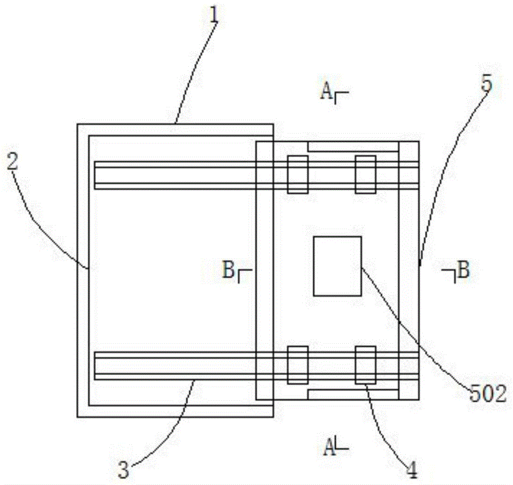
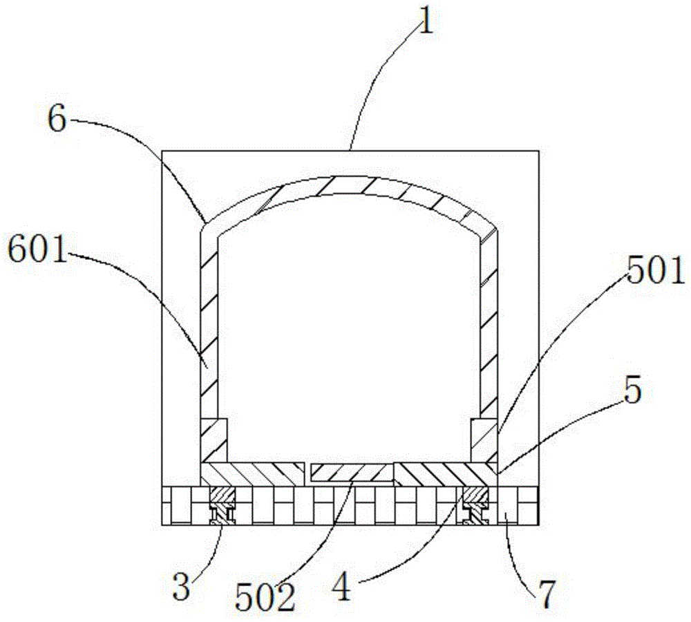
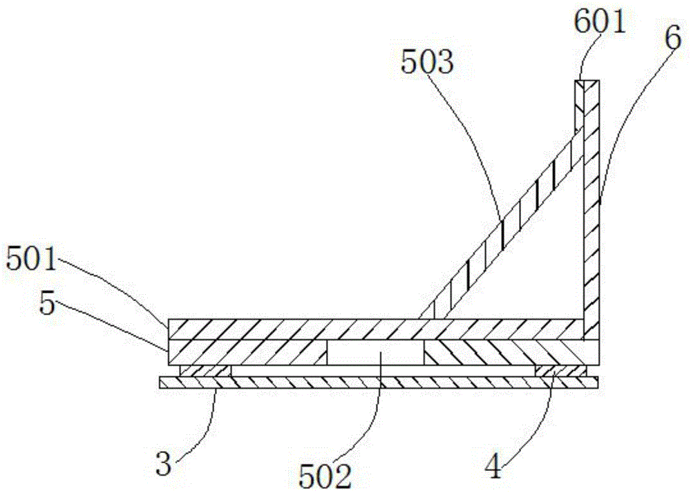
[0023] Such as figure 1 , figure 2 , image 3 As shown, it includes furnace body 1, combustion chamber 2, slide rail 3, pulley 4, placement plate 5, furnace door 6, refractory wall 7, partition 501, movable door 502, reinforcing rib 503, asbestos strip 601, slide rail 3 Located on the left and right sides of the bottom of the combustion chamber 2, the two are connected by threads. The shape is rectangular, the furnace door 6 is located at the right end of the placement plate 5, and the two are connected by welding. The gap at the bottom of the slide rail 3 is also provided with a...


PUM


Abstract

The invention discloses a sliding feeding device which comprises a furnace body, a combustion chamber, sliding rails, sliding wheels, a carrying plate and a furnace door. The sliding rails are located on the left side and the right side of the bottom of the combustion chamber and are in threaded connection with the combustion chamber. The cross sections of the sliding rails are in an I shape. The sliding wheels are located at the upper ends of the sliding rails and are connected with the sliding rails in a sliding manner. The carrying plate is located at the upper ends of the sliding wheels and connected with the sliding wheels in a welded manner, and the carrying plate is rectangular. The furnace door is located at the right end of the carrying plate and is connected with the carrying plate in a welded manner. According to the sliding feeding device, the bottom of the combustion chamber is changed to be movable from a fixed manner, the requirement for incineration of large-size incinerated objects can be met, mechanical casting can also be conveniently achieved, and the incineration efficiency is improved.

Description

technical field [0001] The invention relates to a feeding device, in particular to a sliding feeding device. Background technique [0002] With the rapid development of the economy, more and more garbage is produced, and the popularity of incinerators is also increasing. Generally, the throwing port of the incinerator is fixed, and the furnace door can only be rotated to open and close. Or when needing to focus on rapid incineration, this structure will greatly limit the incineration range, reduce incineration efficiency, and increase labor intensity. In view of the above-mentioned defects, it is necessary to design a sliding feeding device. Contents of the invention [0003] The technical problem to be solved by the present invention is to provide a sliding feeding device to solve the problem that the single structure of the throwing port and the furnace door affects the incineration efficiency. [0004] In order to solve the above technical problems, the technical solut...

Claims


Application Information

Patent Timeline
IPC IPC(8): F23G5/44
Inventor 洪国元汪建华
Owner 池州中宏运环保设备有限公司
Why Eureka
Try Eureka