[0028] Example 1
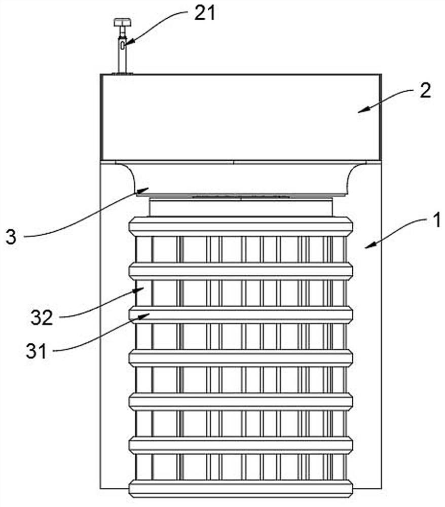
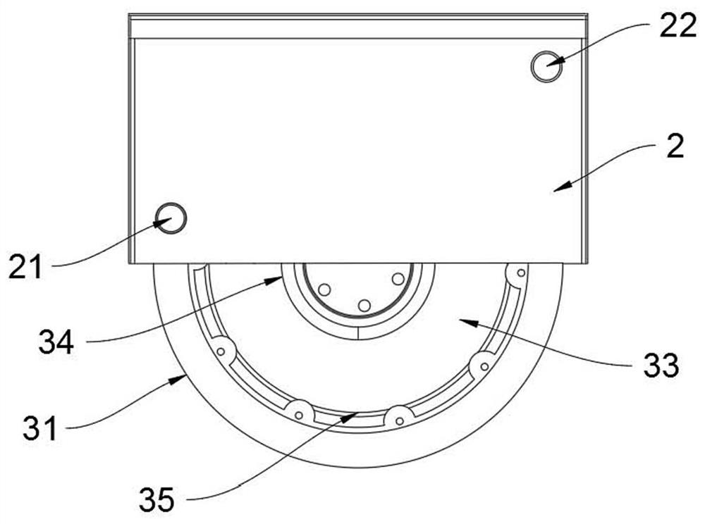
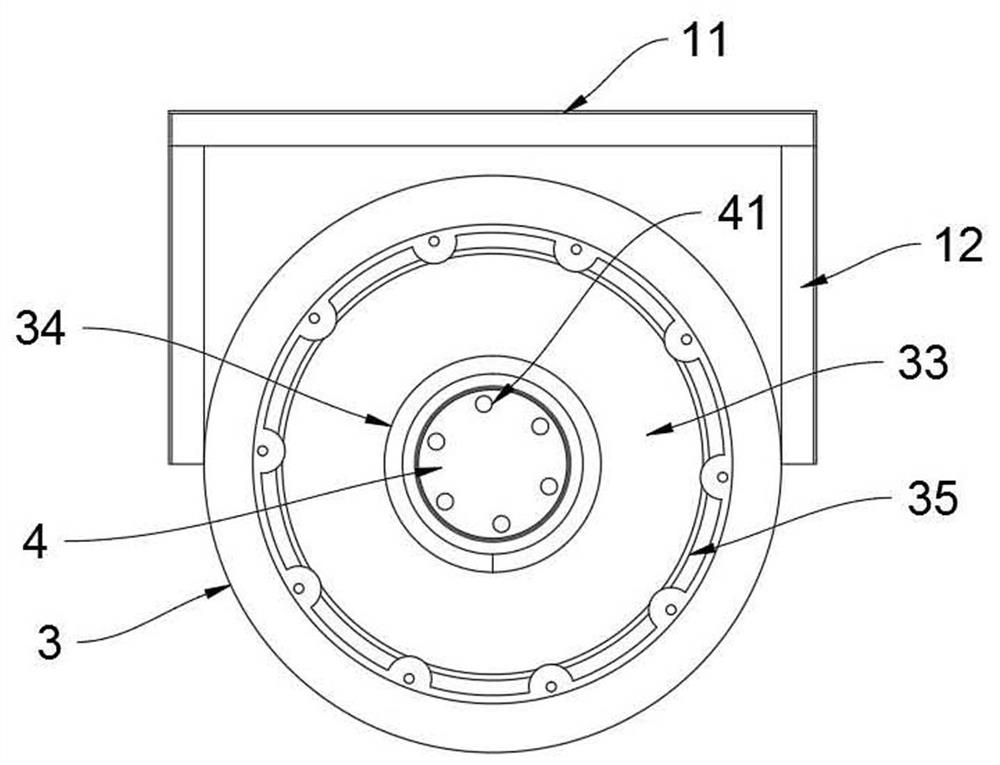
[0029] as Figures 1 through 9As shown, an automated hydrological flood monitoring device suitable for flood-prone areas, comprising an installation bracket 1, an installation bracket 11 comprising a mounting plate 11 and several groups of vertically arranged connecting arms 12, one end of the connecting arm 12 is fixedly connected to the mounting plate 11, the surface of the connecting arm 12 is fixedly connected to the flood trace box 3, the flood trace box 3 includes a spacer 31, several groups of connection arms 12 and the spacer 31 is fixedly connected, the interval frame 31 is actively connected to the transfer pipe member 32, and the surface of the pipe transfer member 32 is provided with a guide plate, Water flow, driving the rotation pipe fittings 32 rotation, the center of the flood trace box 3 is provided with a flood trace tube 34, the upper and lower ends of the flood trace pipe 34 are through, the water enters the flood trace pipe 34 from the bottom of the flood trace pipe 34, the internal of the flood trace pipe 34 is provided with a flood trace plate 4, the flood trace plate 4 monitors the height of the flood trace, the flood trace box 3 is provided with a data collection chamber 33, the data collection chamber 33 is provided with a speed collection device, the speed collection device collects the speed of the transfer pipe part 32, and the upper end of the flood trace box 3 is covered with a motorized box 2, The motor box 2 and the mounting bracket 1 can be removed, the motor box 2 is connected to the speed acquisition device, the surface of the motor box 2 is provided with a communication antenna 21, the internal configuration of the mobile box 2 is provided with a communication module 61, the communication module 61 may transmit the flood trace height data and speed data to the rear computer through the communication antenna 21.
[0030] In the present embodiment, the preferred, may be installed in the wall surface to be installed groove, the mounting bracket 1 installed in the groove, the best, the flood trace box 3 half protruding out of the groove, easy to monitor the flood occurs, the water flow rate, easy to understand the actual flood situation at the specific location, and based on the groove itself, to provide better protection for the electrical devices within the device; For the spacer frame 31 in the device, which adopts a multi-layer setting, the dynamic sealing between each two layers is provided with a rotatable pipe transfer 32, by turning the rotation of the pipe fittings 32, to measure the flow rate of water, the flow rate can be obtained by setting the corresponding sensor, the water surface height of the flood can be obtained by the flood trace plate 4 to assist, the flood trace plate 4 may use a liquid level sensor to assist the measurement, but in the present embodiment, in order to reduce the cost and reduce the information collection port, improve the integration and durability of the device, Provide a new information collection method, through the video acquisition component 7 to achieve the monitoring of flood scar height and flood flow rate monitoring (specific use, can be based on the actual situation to choose to use; The video capture component 7 in the present embodiment is configured in such a way, with reference to the following).
[0031] It should also be noted that the removable connection in the "mobile box 2 and the installation bracket 1 removable connection" may be based on any of the prior art of the detachable connection, the best, or the use of bolts, to facilitate the maneuvering box 2 to provide better stability, at the same time, easy to maintain the replacement of the corresponding accessories, electrical devices, disassembly and use; The door of the motorized box 2 is generally set in the wall position of the side box; The inner cavity of the motorized box 2 is internally connected to the test trace box 3.
[0032] Further illustrate, the flood trace tube 34 is a transparent tube, the data acquisition chamber 33 is provided with a video acquisition component 7 that can be moved up and down along the data acquisition chamber 33, the flood trace plate 4 floats in the liquid surface of the flood trace tube 34, the surface of the flood trace tube 34 is provided with a height scale line, the video acquisition component 7 comprises the collection end 76, the central position of the acquisition end 76 is provided with a horizontal line identification, the video acquisition component 7 collects the position image of the flood trace plate 4 located in the flood trace tube 34, based on the communication module 61 is sent to the back computer.
[0033] In the present embodiment, the surface of the transparent flood trace tube 34 is provided with a height tick line, when the water enters the flood trace box 3 from the bottom, the flood trace plate 4 floats up on the water surface, using a linear component structure, driving the video acquisition component 7 moves up and down in the data acquisition chamber 33 to obtain a position image of the flood trace plate 4, the video acquisition component 7 is the best use of a micro HD camera, and, may be employed in a three-point and one-line manner, through the video acquisition component 7 of the acquisition terminal of the horizontal line identification, The horizontal line identification of the surface of the flood trace pipe 34 and the position of the flood trace plate 4, three points and one line, can accurately obtain the immediate flood trace of the flood; In actual use, can be trained by computer, the use of image recognition system, to obtain the height data of the flood trace, in order to send the corresponding data to the back computer through the communication module 61, the communication module 61 at this time can choose the ZTE AD38123G module, the module wireless connection ability is strong.
[0034] Generally, in actual use, the flood trace plate 4 can use red and other eye-catching colors, and the corresponding small lighting body can be set on the top of the box 2 of the motorized box, but in order to prevent the water quality of the flood is too mixed, especially in the small town villages near the slope of the mountainous area, in order to make the flood trace plate 4 more eye-catching, the sign light 41 can be set on the surface of the flood trace plate 41. Further, the battery may be provided inside the flood trace plate 4 to provide electrical energy to the sign light 41, or, on the surface of the flood trace plate 4 with the connection wire, by connecting the wire, to provide electrical energy to the sign light 41, it should be noted that the connection wire is generally loosely set, will not cause too much impact on the floating of the flood trace plate 4, and one end of the connecting wire is connected to the power supply. The connection wire can obtain electrical energy by the following way, the battery assembly 62 is provided inside the motorized box 2, generally a battery, the connection wire is connected to the battery assembly 62 to obtain electrical energy, the way is generally far away from the main line interface position adopted;
[0035] For some of the motorized box 2 close to the main line interface, the connection wire and other lines of the motor box 2 are summarized, by opening a connection line port 22 on the surface of the motor box 22, through the connection line port 22 and the outside world of the total line interface (the total line interface may refer to a power interface, signal interface, for a pronoun, not referring to a single interface) connected.
[0036] The speed acquisition device is also a video acquisition component 7, the video acquisition component 7 is provided with a vertical line identification at the center of the acquisition end of 76, the data acquisition chamber 33 is provided with a transparent built-in tube 35, the built-in tube 35 isolates the inner wall of the pipe member 32 and the video acquisition component 7, the inner surface of the pipe transfer device 32 is provided with a vertical line identification, and the video acquisition component 7 obtains the speed of the pipe transfer device 32 based on the position of the two sets of vertical line identification.
[0037] Specifically, the video acquisition component 7 may identify the position of the vertical line identification of the video image in the transmutation pipe 32 to obtain the speed of the transpose member 32, the optimal, the video acquisition component 7 identifies the vertical line identification of the transpose member 32 in the multi-frame image, based on the frame number image, to obtain the corresponding time period, in order to obtain the rotation speed of the transistor 32 (within the minimum number of frames, to obtain the two frame images closest to the vertical line identification of the end of the acquisition end 76, in order to obtain the rotation time of the transistor 32).
[0038] Further, the interior of the motorized box 2 is also provided with a drive component 63, the drive component 63 drives the video acquisition component 7 from the bottom of the motorized box 2 to the bottom of the data acquisition chamber 33 or from the data acquisition chamber 33 to the motorized box 2 to move, the acquisition of speed data or flood trace height data.
[0039] Wherein, the drive assembly 63 includes a drive motor, the drive end of the drive motor is fixedly connected to the connecting gear 64, the drive motor is connected to the rotary member 65 by connecting the gear 64, the surface rotation of the rotary member 65 is wound with a coiled first connecting rope 66, and one end of the first connecting rope 66 is fixed to the lower end of the video acquisition component 7 through the guide wheel 5.
[0040] Specifically, the drive assembly 63 includes the following two forms:
[0041] First, the upper end of the video acquisition component 7 is connected to a second connection rope 67, one end of the second connection rope 67 is winded up on the surface of the winding spring, one end of the winding spring is connected to the hinge member, and one end of the hinge member is fixedly connected to the inner wall of the motor box 2; In this scheme, by driving the motor drive the rotary member 65 rotation, so that the first connection rope 66 winding, pull the video acquisition component 7 down, so that the second connection rope 67 passive elongation, in actual use, you can add a drive motor inside the video acquisition component 7, the drive end of the drive motor is connected to the tool structure, and can be set at the bottom of the flood box 3 to detect water seepage, water accumulation sensor assembly, when the flood box 3 appears water seepage, water accumulation problem, The above drive motor drive tool truncates the first connecting rope 66, at this time the entire video acquisition component 7 is subject to the elastic force of the winding spring, moved up to the motor box 2 (the hinge is located in the motor box 2), easy to protect the video acquisition component 7, to cope with the sudden situation during flood trace collection, reduce losses.
[0042]Second, the upper end of the video acquisition component 7 is connected to the second connection rope 67, the second connection rope 67 is reversed to the surface of the rotary member 65, the video acquisition component 7 includes a housing member 71, the inner part of the housing 71 is provided with a sliding cavity 72, the sliding cavity 72 is provided with a collection unit 75 that can be moved up and down along the sliding cavity 72 and rotated, the acquisition end 76 is provided on the side of the acquisition unit 75, and the outer surface of the housing 71 is opened with a collection window 73, The acquisition end 76 is located within the range of the acquisition window 73 to move up and down, the surface of the acquisition unit 75 is fixedly connected to the slider member 77, the sliding cavity 72 is provided with a chute member 74, the slider member 77 is located in the chute 74 sliding; as Figure 8 and Figure 9 As shown, in this scheme, the first connecting rope 66 and the second connecting rope 67 are provided on the surface of the rotary member 65, when the drive motor drives the rotary member 65 to turn, the first connecting rope 66 is unwinded, and the second connecting rope 67 is released; When the drive motor is reversed, the first connecting rope 66 is released, and the second connecting rope 67 is rolled up, and the entire rope body is relatively tight; The scheme, the acquisition end 76 first collects the image of the transfer pipe fittings 32 near the outside, after the shell 71 touches the bottom, as the second connection rope 67 continues to tighten, driving the acquisition unit 75 to move down, so that the slider member 77 on the surface of the acquisition unit 75 slides along the chute 74, so that the acquisition unit 75 rotates 180 °, so that the acquisition end 76 can collect the image of the flood trace tube 34, at this time the drive motor is reversed, which can drive the entire video acquisition component 7 up, thereby obtaining a more accurate position image of the flood trace plate 4.
[0043] It should be noted that the automatic hydrological flood trace monitoring device suitable for flood-prone areas, when in use, the monitoring device is convenient for monitoring the flood occurrence, the water flow speed in the area, and the height of the flood, through the way of video image acquisition, reduce the use of data connectors, improve the integration of the device, and facilitate the improvement of the life of the entire device; The data acquisition chamber 33 in the device through the transparent flood trace tube 34 and the transparent built-in tube 35, that is, improve the measurement accuracy, but also improve the protection performance of the device to the video acquisition component 7; The whole device structure is simple, easy to operate, flexible to use, easy to use, easy to promote the use of flood trace monitoring.