Service architecture generation method and device and electronic equipment

A terminal device, preset action technology, applied in the creation/generation of source code, software engineering design, electrical digital data processing, etc., can solve the problem of low efficiency of service architecture development, achieve low development efficiency and shorten service development. cycle, the effect of improving development efficiency

Pending Publication Date: 2022-06-07
NETEASE HANGZHOU NETWORK
0 Cites 0 Cited by

AI-Extracted Technical Summary

Problems solved by technology

[0004] The purpose of this application is to provide a service architecture generation method, device and electron...

Method used

By making the system analyze and run the service behavior in the service architecture through the engine based on the workflow model, the reuse of the functional nodes of the workflow model and the advantages of low error rate and high stability can be used to analyze and run the service behavior through the engine based on the workflow model , making the development and operation of the service architecture more stable and efficient.
[0054] Based on this, the embodiment of the present application provides a service architecture generation method, device and electronic equipment. The method uses a mode of automatically generating and loading services to replace a series of organizational structures, writing service codes, debugging, and deploying online. link, which greatly shortens the service development cycle, and has the advantages of WYSIWYG, flexible configuration, rapid service generation, self-service operation and maintenance, automatic statistical reporting, and automatic integration of various common tools; at the same time, using the reuse of functional nodes of the workflow model, It also has the advantages of low error rate and high stability; and, with the continuous expansion of functional nodes, the use value and development efficiency of this system will also be greatly improved. Developers only need to expand the missing functional nodes into the system The node space, and define the node DAG flow chart, you can get the required service API interface, realize codeless service API generation, to alleviate the technical problem of low service architecture development efficiency in the existing technology.
[0084] By making the system first respond to the user's first selection operation for several preset action contents, determine the target preset action content corresponding to the first selection operation, and then determine in response to the user's second selection operation for several service actions The second selection operation corresponds to the target service action, so that the target preset action content is determined as the action content corresponding to the target service action, so that the user can more accurately determine the action content corresponding to the target service action, thereby improving service architecture development. efficiency.
[0090] Exemplarily, the logical node graph includes a directed complete graph, a directed program flow chart, a directed acyclic graph, and the like. DAG graph is a directed acyclic graph, which is a commonly used data structure in the computer field. The unique topological structure has unique excellent characteristics, and is often used to deal with various algorithm scenarios such as dynamic programming, finding the shortest path in navigation, and data compression. . DAG can theoretically achieve distribution and high efficiency. Compared with other logical node graphs, DAG graphs are clearer and more intuitive. Workflow refers to "automation of a p...

Abstract

The invention provides a service architecture generation method and apparatus, and an electronic device, relates to the technical field of service architecture development, and solves the technical problem of low service architecture development efficiency in the prior art. The method comprises the following steps: in response to a first editing operation for nodes, determining an inter-node time sequence and an inter-node logic rule corresponding to the first editing operation in a logic node graph through an XPDL specification; wherein service actions are correspondingly loaded in the nodes; in response to a second editing operation for the service action, determining action content corresponding to the second editing operation; and splicing the action contents corresponding to the plurality of service actions according to the inter-node time sequence and the inter-node logic rule to generate the service architecture.

Application Domain

Intelligent editorsVisual/graphical programming

Technology Topic

EngineeringComputer network +5

Image

  • Service architecture generation method and device and electronic equipment
  • Service architecture generation method and device and electronic equipment
  • Service architecture generation method and device and electronic equipment

Examples

  • Experimental program(1)

Example Embodiment

[0048]In order to make the purposes, technical solutions and advantages of the embodiments of the present application more clear, the technical solutions of the present application will be described clearly and completely below with reference to the accompanying drawings. Obviously, the described embodiments are part of the embodiments of the present application, not all of them. example. Based on the embodiments in the present application, all other embodiments obtained by those of ordinary skill in the art without creative efforts shall fall within the protection scope of the present application.
[0049] The terms "comprising" and "having" mentioned in the embodiments of the present application and any modifications thereof are intended to cover non-exclusive inclusion. For example, a process, method, system, product or device comprising a series of steps or units is not limited to the listed steps or units, but optionally also includes other unlisted steps or units, or optionally also Include other steps or units inherent to these processes, methods, products or devices.
[0050] In the current service architecture development technology, the service division is becoming more and more refined, but it still cannot go beyond the traditional process of "propose requirements" - "design architecture" - "divide services" - "iterative development" - "test deployment". Existing background technology architectures tend to be more friendly to developers and improve team development efficiency, but lack demand-side-friendly, quick-response, self-service, and WYSIWYG service acquisition solutions. Separate the process formulation process of the requester and the iterative development process of the developer, so that the two do not interfere with each other, and enrich and develop the business system in parallel.
[0051] Existing solutions to quickly realize service development or generation include technical solutions or standards such as agile development, dividing service nodes by microservices, or using configuration files to generate services. Agile development is a human-centered, iterative, step-by-step development method. In agile development, the construction of a software project is divided into multiple sub-projects, and the results of each sub-project are tested and have the characteristics of integration and operation. In other words, it is to divide a large project into multiple small projects that are interconnected but can also run independently, and complete them separately. During this process, the software is always in a usable state. Microservices break down traditional giant monolithic services into small, interconnected microservices. A microservice completes a specific function. Each microservice has its own business logic and adapters. Some microservices can also provide API interfaces for other microservices and application clients to use.
[0052] However, although the traditional development efficiency optimization specifications such as agile development have solved the problem of cooperation efficiency of the development team to a certain extent, they have not effectively improved the effective splitting, combination and reuse of service nodes, automatic generation and deployment of services, etc. Today's fast-growing Internet service needs. Microservice architecture focuses on service governance, and is dedicated to solving complexity problems (decomposing traditional monolithic architecture), team efficiency problems (each service can be independently developed by a team dedicated to this service), and seamless upgrades through refined architecture division. Problems (the microservice architecture can enable each microservice to be deployed independently) and other practical needs. The existing technical solutions based on configuration file template reuse and other technical solutions improve the efficiency of service generation to a certain extent through the form of configuration file reuse, and realize the re-generation of similar services through configuration template reuse, but they are not fully capable of splitting. The process formulation process of the requirement proposer and the ability of the developer to iterate the development process also do not have the ability to generate new services by WYSIWYG.
[0053] It can be seen from the above defects that there is a technical problem of low efficiency of service architecture development for the existing service architecture development technology.
[0054] Based on this, the embodiments of the present application provide a method, device, and electronic device for generating a service architecture. The method uses a mode of automatically generating and loading services to replace a series of links such as organizational architecture, writing service code, debugging, and deploying online. The service development cycle is shortened, and it has the advantages of WYSIWYG, flexible configuration, rapid service generation, self-service operation and maintenance, automatic statistical reporting, and automatic integration of various common tools; at the same time, the reuse of functional nodes using the workflow model also has the advantages of low cost. The advantages of error rate and high stability; and, with the continuous expansion of functional nodes, the use value and development efficiency of the system will also be greatly improved, and developers only need to expand the missing functional nodes into the node space of the system. , and define the node DAG flow chart, the required service API interface can be obtained, and the codeless service API generation can be realized, so as to alleviate the technical problem of low service architecture development efficiency in the prior art.
[0055] In one of the embodiments of the present application, the method for generating a service architecture may run on a local terminal device or a server. When the service architecture generation method runs on the server, the method can be implemented and executed based on a cloud interaction system, wherein the cloud interaction system includes a server and a client device.
[0056] For example, as figure 1 shown, figure 1 This is a schematic diagram of an application scenario provided by this embodiment of the present application. The application scenario may include a terminal device 102 and a server device 101, and the terminal device 102 may communicate with the server device 101 through a wired network or a wireless network. The electronic device in this embodiment may be the terminal device 102 or the server device 101 .
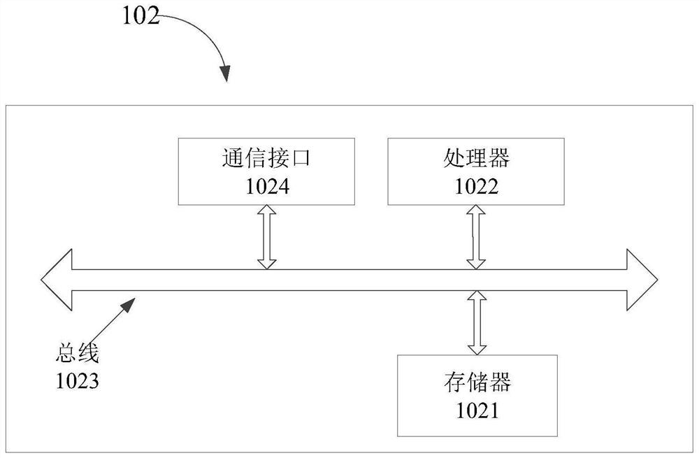
[0057] The middle electronic device in this embodiment is described by taking the terminal device 102 as an example. like figure 2 As shown, the terminal device 102 includes a memory 1021 and a processor 1022. The memory stores a computer program that can be run on the processor. When the processor executes the computer program, the methods provided in the above embodiments are implemented. step.
[0058] see figure 2 , the terminal device 102 also includes: a bus 1023 and a communication interface 1024, the processor 1022, the communication interface 1024 and the memory 1021 are connected through the bus 1023; the processor 1022 is used for executing executable modules stored in the memory 1021, such as computer programs.
[0059] The memory 1021 may include a high-speed random access memory (Random Access Memory, RAM for short), and may also include a non-volatile memory (non-volatile memory), such as at least one disk memory. The communication connection between the network element of the system and at least one other network element is realized through at least one communication interface 1024 (which may be wired or wireless), which may use the Internet, a wide area network, a local network, a metropolitan area network, and the like.
[0060] The bus 1023 may be an ISA bus, a PCI bus, an EISA bus, or the like. The bus can be divided into an address bus, a data bus, a control bus, and the like. For ease of presentation, figure 2 is represented by a double-headed arrow, but does not imply that there is only one bus or one type of bus.
[0061] The memory 1021 is used to store a program, and the processor 1022 executes the program after receiving the execution instruction, and the method executed by the device defined by the process disclosed in any of the foregoing embodiments of the present application can be applied to the processor 1022 , or implemented by the processor 1022.
[0062] The processor 1022 may be an integrated circuit chip with signal processing capability. In the implementation process, each step of the above-mentioned method can be completed by an integrated logic circuit of hardware in the processor 1022 or an instruction in the form of software. The above-mentioned processor 1022 may be a general-purpose processor, including a central processing unit (Central Processing Unit, CPU for short), a network processor (Network Processor, NP for short), etc.; it may also be a digital signal processor (Digital Signal Processing, DSP for short) , Application Specific Integrated Circuit (ASIC for short), Field-Programmable Gate Array (FPGA for short) or other programmable logic devices, discrete gate or transistor logic devices, and discrete hardware components. The methods, steps, and logic block diagrams disclosed in the embodiments of this application can be implemented or executed. A general purpose processor may be a microprocessor or the processor may be any conventional processor or the like. The steps of the method disclosed in conjunction with the embodiments of the present application may be directly embodied as executed by a hardware decoding processor, or executed by a combination of hardware and software modules in the decoding processor. The software modules may be located in random access memory, flash memory, read-only memory, programmable read-only memory or electrically erasable programmable memory, registers and other storage media mature in the art. The storage medium is located in the memory 1021, and the processor 1022 reads the information in the memory 1021, and completes the steps of the above method in combination with its hardware.
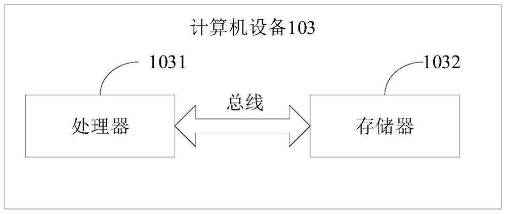
[0063] Of course, the electronic device in this embodiment may also be a local computer device without network connection. like image 3 As shown, the computer device 103 includes: a processor 1031, a memory 1032, and a bus, the memory 1032 stores machine-readable instructions executable by the processor 1031, and when the electronic device is running, the processor 1031 communicates with all The memory 1032 communicates through a bus, and the processor 1031 executes the machine-readable instructions to execute the steps of the method for generating a service architecture.
[0064] Specifically, the above-mentioned memory 1032 and processor 1031 can be general-purpose memories and processors, which are not specifically limited here. When the processor 1031 runs the computer program stored in the memory 1032, it can execute the service architecture generation method.
[0065] The embodiments of the present application will be further introduced below with reference to the accompanying drawings.
[0066] Figure 4 A schematic flowchart of a method for generating a service architecture provided by an embodiment of the present application. The method can provide a graphical user interface through a terminal device, the content displayed on the graphical user interface includes at least part of the logical node graph, and the logical node graph includes nodes described based on the XPDL specification, such as Figure 4 As shown, the method includes:
[0067] Step S410, in response to the first editing operation on the node, determine the inter-node timing sequence and the inter-node logic rule corresponding to the first editing operation in the logical node graph through the XPDL specification.
[0068] The service actions are correspondingly loaded in the nodes.
[0069] Exemplary as Figure 5 As shown, the user can perform the first editing operation for the nodes in the logical node graph, and assemble the service actions such as start, behavior, decision, and end loaded in the node in a certain logical order to describe the timing and logical rules, and then realize the Inter-node timing and editing of logic rules. Through editing, the entire process can first perform action A, and then make corresponding decision A for action A, split action A into action B and action C, and then obtain the process result.
[0070] The nodes in the embodiments of the present application are divided into process control nodes (for example, nodes such as start, end, decision, branch, and merge) and action execution nodes. The basic syntax format of the nodes follows the XPDL specification protocol, which is a standardized specification. It is designed to meet the business process definition for exchange both graphically and semantically. It is the best file format for describing business process modeling and annotation. However, XPDL not only contains the description of the process execution, but also includes the graphic information of the elements, which is more suitable. in business process modeling. By defining a node description language XPDL, through the abstraction of business behavior, the input, parameter items and operation result output of different nodes in the business process can be described accurately and flexibly.
[0071]Exemplarily, some characteristic syntaxes are as follows: "global", corresponding to the global declaration area, defines the global configuration, all func operators of the configuration can be obtained through the global attribute; "Configuration", corresponding to the start and end character of the configuration definition, according to the requirements of the process. The option determines the attribute name and attribute value of the configuration definition area; "name-space", corresponding to the namespace, after the code engine reads this field, it can switch to the corresponding namespace, and then load the corresponding method in the next step; "func", Corresponding to the method name, after the code engine reads the name, it takes out the method from the namespace and loads it into the running environment; "arg", corresponds to the method parameter definition area; "arg.name", corresponds to the method parameter name; "arg.type", Corresponding to the method parameter type, the code engine obtains the corresponding method input parameters from the configuration (configuration), output (output), static value (static), and request parameter (VAR) in combination with the parameter name and type; "output", the corresponding method output definition area; "output.name", corresponding to the field name output by the method, the code engine will assign the specified name to the return value of the method in the order of definition, and put it into the output space for other control nodes or behavior nodes to use; "ok to", the next node to go to when the corresponding method runs successfully and the status value is true; "error to", the next node to go to when the method runs successfully but the status value is not true; "exception to", corresponding to the next node when the method fails to run; "decision", corresponding to the branch decision node in the control node, which is an important control component in the process execution process; "operator", corresponding to the operator definition; "decision. switch.case.func", corresponding to the specified execution method of the control node, which is consistent with the func operator syntax specification. If the status in the return is true, the process corresponding to the case is executed; "case.arg", corresponding to the specified execution method of the control node or Operator parameters, consistent with the syntax specification of the arg parameter definition area.
[0072] Step S420, in response to the second editing operation for the service action, determine the action content corresponding to the second editing operation.
[0073] Exemplary as Figure 5 As shown, the user can perform a second editing operation for each service action, so as to determine the action content corresponding to the second editing operation. The user can assign different specific action contents to service actions such as action A, decision A, action B, and action C by editing.
[0074] Step S430: Assemble action contents corresponding to several service actions according to the inter-node time sequence and inter-node logic rules to generate a service architecture.
[0075] Exemplary as Figure 5 As shown, after the user has edited the inter-node sequence and inter-node logic rules, and determined the action content corresponding to several service actions, the system can automatically convert some service actions corresponding to the user-edited inter-node sequence and inter-node logic rules. The action content is assembled to generate a complete service architecture.
[0076] By editing the sequence, logic and service actions of the XPDL specification nodes in the logical node diagram, the service architecture can be automatically assembled and generated according to these editing results. The developer only needs to expand the function nodes and define the node flow chart to realize the generation of the service architecture. , replacing the above series of links with the mode of automatically generating and loading services, shortening the service development cycle and improving the efficiency of service architecture development.
[0077] In the embodiment of the present application, the mode of automatically generating and loading services is used to replace a series of links such as organizational structure, writing service code, debugging, and deploying online, which greatly shortens the service development cycle, and has WYSIWYG, flexible configuration, and rapid generation. The advantages of service, self-service operation and maintenance, automatic statistical reporting, and automatic integration of various common tools; with the continuous expansion of functional nodes, developers only need to expand the missing functional nodes into the node space of the system, and define the logical node graph, The required service application program interface (Application Programming Interface, API) can be obtained, and the no-code (Nocode) service API generation can be realized, which improves the development efficiency of the service architecture and alleviates the low development efficiency of the service architecture in the prior art. technical problem.
[0078] The above steps are described in detail below.
[0079] In some embodiments, the user can edit each service action individually, so as to more accurately determine the action content corresponding to the target service action. For example, the user can first select the action content preset in advance, and then select Corresponding target service action to quickly and efficiently complete the determination of the action content. As an example, the display content of the graphical user interface also includes preset action content; the above step S420 may specifically include the following steps:
[0080] Step a), in response to a first selection operation for several preset action contents, determining a target preset action content corresponding to the first selection operation.
[0081] Step b), in response to a second selection operation for several service actions, determining a target service action corresponding to the second selection operation.
[0082] Step c), determining the target preset action content as the action content corresponding to the target service action.
[0083] Exemplarily, the system may display several preset action contents on the graphical user interface, and these preset action contents constitute a node pool, and the user can select the required action contents in the node pool and assign it to a specified action. Taking the process of "going out" as an example, the graphical user interface displays a logical node graph, which includes specific actions such as action A, action B, and action C. The display content of the GUI also includes preset actions such as "getting up", "dressing" and "opening the door". The user can first select the action content of "getting up", determine "getting up" as the target preset action content, and then select action A, then action A can be determined as the corresponding target service action. The system is based on the user's selection. , and "getting up" can be determined as the action content corresponding to action A.
[0084] By causing the system to first determine the target preset action content corresponding to the first selection operation in response to the user's first selection operation for several preset action contents, and then determine the second selection in response to the user's second selection operation for several service actions The corresponding target service action is operated to determine the target preset action content as the action content corresponding to the target service action, so that the user can more accurately determine the action content corresponding to the target service action, thereby improving the service architecture development efficiency.
[0085] Based on the above steps a), b) and c), the user can more conveniently and consistently determine the action content corresponding to the target service action by sliding operations. For example, the user can directly select the target preset action content By connecting the sliding operation and selecting the corresponding target service action, precise editing can be achieved more conveniently and quickly. As an example, the above step c) may specifically include the following steps:
[0086] Step d), in response to the sliding operation of sliding to several service actions continuously with the first selection operation, determine the target service action corresponding to the end of the sliding operation from the several service actions.
[0087] Exemplarily, after the user selects the target preset action content in the node pool through the first selection operation, the determination of the target service action can be realized through continuous sliding operations. Taking the process of "going out" as an example, the user can first click on the action content of "getting up", then slide the mouse, and slide the mouse cursor over action A, then action A can be determined as the corresponding target service action. The user's selection can determine "getting up" as the action content corresponding to action A.
[0088] By making the system respond to the sliding operation of the user and the first selection operation continuously sliding to several service actions, and determine the target service action corresponding to the end of the sliding operation from the several service actions, the user can make the sliding operation more convenient and coherent. It realizes the determination of the action content corresponding to the target service action, reduces the operation steps, and improves the service architecture development efficiency.
[0089] In some embodiments, the logical node graph may include multiple types to make editing operations more flexible, so as to create and edit the service architecture in multiple flexible forms, and assemble the service process through the DAG graph based on the workflow model, And then more efficient realization of the development of the service architecture. As an example, the logical node graph is a DAG graph; the service architecture is a service process assembled through the DAG graph based on the workflow model.
[0090] Exemplarily, the logical node graph includes a directed complete graph, a directed program flow chart, a directed acyclic graph, and the like. DAG graph is a directed acyclic graph, which is a common data structure in the computer field. The unique topology structure has unique excellent characteristics. It is often used to deal with various algorithm scenarios such as dynamic programming, finding the shortest path in navigation, and data compression. . DAG can theoretically achieve distribution and efficiency. Compared with other logical node graphs, DAG graphs are more clear and intuitive. Workflow refers to "the automation of a part or the whole of a business process in a computer application environment". It is an abstract and general description of the business rules between the workflow and its various operation steps. The main problem solved by Workflow is: in order to achieve a certain business goal, use a computer to automatically transfer documents, information or tasks among multiple participants according to certain predetermined rules, by decomposing the work into well-defined tasks or roles, according to Certain rules and procedures are used to perform these tasks and monitor them, so as to improve work efficiency, better control processes, enhance customer service, and effectively manage business processes.
[0091] In practical applications, such as Image 6 As shown, the functions of each module component are as follows. DAG UI (DAG UI) is a user operation interface, communicates with Node Manager to obtain all current valid nodes, and submits new service generation tasks to Node Manager according to user selection and assembly. When the node management communicates with the DAG user interface, it organizes and maintains the node pool, organizes the configuration, input, and output required by the overall service process according to the configuration, input, and output defined by the node, and generates API documents; and the runtime engine (Runtime Engine) During communication, the XDPL file described by the DAG node is serialized into a service object and loaded into the engine to run. The hypertext transfer protocol proxy (HTTP Proxy) communicates with the runtime engine and forwards the external request to the idle work queue. The runtime engine running in the work queue loads the corresponding service DAG model according to the request path and input parameters. Put into operation and return processing results. The Node Pool is used to maintain the logical nodes contributed by each developer in the development architecture. The Node Pool has a global namespace. Each node needs to declare its own running code, input parameters, and configuration requirements (the user side submits the configuration, and the Node management configuration items generated after initialization, etc.). The Developer Toolkits are used to maintain the submission specification of the node configuration, and check, submit and modify the logical nodes in the node pool according to the code submitted by the developer or development team. The Log Hub is used for external log monitoring and alarm synchronization, and is compatible with common log synchronization standards. Database (Database) is divided into system runtime library and each service runtime library. Among them, the system runtime library saves basic information such as permissions and user roles in the system and the serialized service DAG node data; the service runtime library saves each service generated by the user. Online business data generated by the request. The Data Service Platform is used to provide users and administrators with a self-service background, provide business statistics reports, service online and offline management, service business configuration adjustment, and provide a set of APIs for pulling service data for third-party external services .
[0092]By defining a workflow model object, a DAG diagram composed of indeterminate nodes is used to combine and define business processes, and serialize and save them. When services are called, they are dynamically loaded into the system engine to execute specific service business processes. Compared with traditional The development mode uses the reuse of the functional nodes of the workflow model, which has the advantages of low error rate and high stability; and, with the continuous expansion of functional nodes, the use value and development efficiency of this system will also be greatly improved. Users Just expand the missing function nodes into the node space of the system and define the node DAG flow chart to obtain the required service API interface, which effectively improves the development efficiency of the service architecture.
[0093] In some embodiments, the service architecture can be displayed more clearly and intuitively through the DAG diagram, and the advantages of the DAG can be used to greatly improve the expansibility of the service architecture, so that the user can freely create the service architecture and improve the development efficiency. As an example, after the above step S430, the method may further include the following steps:
[0094] Step e), displaying the service architecture through the DAG diagram in the graphical user interface.
[0095] Exemplary as Figure 7 As shown, the core technical idea is to compare the complete process of requirements to "behavior", and "behavior" is composed of multiple single "actions" according to different "sequences" and "rule strategies". By abstracting the functional modules into "actions", the "action library" can be obtained as the basic capability range, and then different nodes are assembled through the logical node diagram to describe the "sequence", and the dynamically generated instance configuration table is used to describe the "rule strategy" , a complete requirement will be effectively disassembled.
[0096] By using the DAG diagram, a service process can be divided into multiple actions, and then the DAG diagram can be used to describe the timing dependencies between the actions, in which each action is an independent, non-splittable functional module encapsulated by the business party , which realizes a hot-plug mechanism that can expand functional nodes at any time without stopping, and generates new types of service APIs by freely defining the timing and dependencies between nodes into different DAG flow charts, thereby making editing operations more flexible. , in order to realize the creation and editing of the service architecture through a variety of flexible forms, and improve the development efficiency of the service architecture.
[0097] In some embodiments, the reuse of functional nodes of the workflow model and the advantages of low error rate and high stability can be used to parse and run service behaviors through the engine based on the workflow model, so that the development and operation of the service architecture are more stable and efficient. As an example, after the above step S430, the method may further include the following steps:
[0098] Step f), parse and run the service behavior in the service architecture through the engine based on the workflow model.
[0099] Exemplary as Figure 8 As shown, the business department or R&D uses the DAG user interface, selects the corresponding demand process, and the development platform automatically synthesizes the corresponding instance DAG description and configuration text, which is received by the node management and serialized and saved to the Instance Conf Center. The new service instance has been successfully generated, and the service interface can be provided externally. When the external request arrives, the proxy resolves to the instance code corresponding to the request, and the runtime manager obtains and encapsulates the workflow model (DAG+configuration) corresponding to the instance from the configuration center according to the instance code, and pushes the model to the runtime engine to load, the engine After loading, the running nodes are loaded one by one according to the time sequence and rule configuration until the final output result is obtained, which is encapsulated into serialized request response data by the runtime manager, and finally presented to the user in the form of an interface response to complete a complete service. Instance response.
[0100] By making the system parse and run the service behavior in the service architecture through the engine based on the workflow model, the reuse of the functional nodes of the workflow model and the advantages of low error rate and high stability can be used to parse and run the service behavior through the engine based on the workflow model, so that the service The development and operation of the architecture are more stable and efficient.
[0101] In some embodiments, the user may also save the created service architecture as a template for use by himself or other users, thereby further improving development efficiency. For example, the user can save the node assembly sequence of the common demand service as a template and save it to the database. As an example, after the above step S430, the method may further include the following steps:
[0102] Step g), in response to the sharing operation for the service schema, storing at least part of the service schema as a template in a template database.
[0103] Exemplary as Figure 9 As shown, business party A selects the required nodes through the DAG user interface and assembles the timing and condition configuration. After the new service architecture is finally generated, the node management saves the workflow description file of the service into the database, and then business party A can choose whether to open or partially Open Process Template. If business A chooses not to share the template, the system renders the service, generates an XPDL file, and saves it to the model running engine. If business party A chooses to share the template, other business parties can view the complete DAG composition of the service in the DAG user interface, and choose to reuse the entire service or select some branches as sub-processes.
[0104] By making the system respond to the user's shared operation for the service architecture, at least part of the service architecture is stored in the template database as a template, so that with the support of an open technical architecture, with the continuous expansion of nodes and the continuous generation of services of different business types, Template-based preservation and reuse of the node assembly sequence of common demand services to further improve the efficiency of service generation.
[0105] Based on the above step g), the user can also select the existing service architecture corresponding to the demand from the database, and reuse it directly without re-development of the service architecture, which effectively shortens the development cycle and improves the development efficiency. As an example, after the above step g), the method may further include the following steps:
[0106] Step h), in response to the third selection operation on the service schema in the template database, determine to obtain the service schema from the template database, and run the engine based on the service schema.
[0107] Exemplary as Figure 9 As shown, business party B may choose to create a service architecture by template loading. Business party B first selects the target function category in the template pool, and then selects the desired template to load. If the template completely meets the needs of business party B, business party B can choose to directly render the service through the system to generate a new XPDL file And save it to the model running engine.
[0108] By making the system respond to the user's third selection operation on the service architecture in the template database, determine to obtain the service architecture from the template database, and run the engine based on the service architecture, so that the user can select the existing service architecture corresponding to the demand from the database. , directly reuse without having to re-develop the service architecture, which effectively shortens the development cycle and improves the development efficiency.
[0109] Based on the above step h), the user can also flexibly edit the existing service architecture template in the database, and after selecting the template, add or delete the template based on the target requirements, so as to make it meet the target requirements, not only make The use of templates is more flexible, and it also effectively shortens the development cycle and improves development efficiency. As an example, the part of running the engine based on the service architecture in the above step h) may specifically include the following steps:
[0110] Step i), in response to the third editing operation on the service schema, running the engine based on the service schema result edited by the third editing operation.
[0111] Exemplary as Figure 9 As shown, business party B may choose to create a service architecture by template loading. Business party B first selects the target function category in the template pool, and then selects the desired template to load. After that, business party B can choose to supplement the template process, that is, first select the backplane from the template pool, and then modify the actual process. Business party B can load the workflow to the DAG user interface, and enter the service to modify and add. After modification, the service can be rendered through the system, and a new XPDL file can be generated and saved to the model running engine.
[0112] By making the system respond to the user's third editing operation on the service architecture, and run the engine based on the service architecture result edited by the third editing operation, the user can flexibly edit the existing service architecture template in the database, and when the selected service architecture template is selected. After the template, the template is modified based on the target requirements, such as adding or deleting, so as to meet the target requirements, which effectively shortens the development cycle and improves the development efficiency.
[0113] Based on the above step i), the above-mentioned third editing operation modes for the service architecture can be various, so that the editing operation is more flexible. For example, the third editing operation can include multiple types, so as to realize the editing of the service architecture through multiple flexible types. . Exemplarily, the third editing operation includes any one or more of the following:
[0114] The modification operation of the service architecture, the selection operation of at least part of the service architecture, the operation of combining at least part of the service architecture with the specified architecture, and the confirming use operation of all the service architectures.
[0115] As an example, the service architecture in the template includes part A, part B, and part C. After selecting the template from the template pool, the user can modify the template, and modify the service architecture in the template based on the target to meet the target requirements, for example , modify Part C to Part D, so that the new service architecture includes Part A, Part B, and Part D.
[0116] As another example, the user can also select part of the service architecture in the template, that is, only part of the content in the template is needed to achieve the target requirement. For example, the user only selects part A and part B, but does not select part C, so that The service architecture includes only part A and part B.
[0117] As another example, the user can also combine at least part of the service schema in a template with the specified schema, for example, combine parts A, B, and C with part E in the specified schema, so that a new service The architecture includes Part A, Part B, Part C, and Part E.
[0118] As another example, the user can also confirm the use of all service architectures, that is, completely apply the template to the service architecture, so that the new service architecture includes part A, part B, and part C.
[0119] By making the third editing operation mode include multiple types, the user can perform multiple editing operations on the template, so as to realize the flexible editing of the template service architecture through multiple types, so that the service architecture is more in line with the target requirements.
[0120] Figure 10 A schematic structural diagram of a service architecture generating apparatus 1000 is provided. Wherein, the apparatus provides a graphical user interface through a terminal device, the content displayed on the graphical user interface includes at least part of a logical node graph, and the logical node graph includes nodes described based on the XPDL specification. like Figure 10 , the service architecture generating apparatus 1000 includes:
[0121] The first determining module 1001 is configured to, in response to the first editing operation for the node, determine the inter-node timing sequence and the inter-node logic rule corresponding to the first editing operation in the logical node graph by using the XPDL specification; wherein, the node is correspondingly loaded with a service action.
[0122] The second determining module 1002 is configured to, in response to the second editing operation for the service action, determine the action content corresponding to the second editing operation.
[0123] The assembling module 1003 is configured to assemble the action contents corresponding to several service actions according to the inter-node sequence and inter-node logic rules to generate a service architecture.
[0124] In some embodiments, the display content of the graphical user interface further includes preset action content; the second determining module 1002 is specifically configured to:
[0125] In response to a first selection operation for several preset action contents, determining a target preset action content corresponding to the first selection operation;
[0126] In response to a second selection operation for several service actions, determining a target service action corresponding to the second selection operation;
[0127] The target preset action content is determined as the action content corresponding to the target service action.
[0128] In some embodiments, the second determining module 1002 is specifically configured to:
[0129] In response to a swipe operation of swiping to several service actions consecutive to the first selection operation, a target service action corresponding to the end of the swipe operation is determined from the several service actions.
[0130] In some embodiments, the logical node graph is a DAG graph; the service architecture is a service process assembled through the DAG graph based on the workflow model.
[0131] In some embodiments, the apparatus further includes:
[0132] The display module is used to assemble the action contents corresponding to several service actions according to the inter-node sequence and inter-node logic rules, and after the service architecture is generated, the service architecture is displayed through the DAG diagram in the graphical user interface.
[0133] In some embodiments, the apparatus further includes:
[0134] The parsing module is used to assemble the action contents corresponding to several service actions according to the inter-node sequence and inter-node logic rules. After generating the service architecture, the engine parses and runs the service behavior in the service architecture based on the workflow model.
[0135] In some embodiments, the apparatus further includes:
[0136] The storage module is used to assemble the action contents corresponding to several service actions according to the time sequence between nodes and the logic rules between nodes, and after the service architecture is generated, in response to the sharing operation for the service architecture, at least part of the service architecture is stored in the template as a template database.
[0137] In some embodiments, the apparatus further includes:
[0138] The third determining module is configured to, in response to the sharing operation on the service architecture, store at least a part of the service architecture as a template in the template database, and then determine to obtain from the template database in response to a third selection operation on the service architecture in the template database Service architecture, and run the engine based on the service architecture.
[0139] In some embodiments, the third determining module is specifically used for:
[0140] In response to the third edit operation on the service schema, the engine is run based on the service schema results edited by the third edit operation.
[0141] In some embodiments, the third editing operation includes any one or more of the following:
[0142] The modification operation of the service architecture, the selection operation of at least part of the service architecture, the operation of combining at least part of the service architecture with the specified architecture, and the confirming use operation of all the service architectures.
[0143] The apparatus for generating a service architecture provided by the embodiment of the present application has the same technical features as the method for generating a service architecture provided in the above-mentioned embodiments, so it can also solve the same technical problem and achieve the same technical effect.
[0144] Corresponding to the above-mentioned method for generating a service architecture, an embodiment of the present application further provides a computer-readable storage medium, where the computer-readable storage medium stores computer-executable instructions, and the computer-executable instructions are called and executed by a processor. , the computer-executable instructions cause the processor to execute the steps of the above-mentioned service architecture generation method.
[0145] The apparatus for generating a service architecture provided by the embodiments of the present application may be specific hardware on the device or software or firmware installed on the device, or the like. The implementation principles and technical effects of the devices provided in the embodiments of the present application are the same as those in the foregoing method embodiments. For brief description, for the parts not mentioned in the device embodiments, reference may be made to the corresponding content in the foregoing method embodiments. Those skilled in the art can clearly understand that, for the convenience and brevity of the description, the specific working processes of the systems, devices and units described above can all refer to the corresponding processes in the above method embodiments, which will not be repeated here.
[0146] In the embodiments provided in this application, it should be understood that the disclosed apparatus and method may be implemented in other manners. The apparatus embodiments described above are only illustrative. For example, the division of the units is only a logical function division. In actual implementation, there may be other division methods. For example, multiple units or components may be combined or Can be integrated into another system, or some features can be ignored, or not implemented. On the other hand, the shown or discussed mutual coupling or direct coupling or communication connection may be through some communication interfaces, indirect coupling or communication connection of devices or units, which may be in electrical, mechanical or other forms.
[0147] As another example, the flowchart and block diagrams in the Figures illustrate the architecture, functionality, and operation of possible implementations of apparatuses, methods and computer program products according to various embodiments of the present application. In this regard, each block in the flowchart or block diagrams may represent a module, segment, or portion of code that contains one or more functions for implementing the specified logical function(s) executable instructions. It should also be noted that, in some alternative implementations, the functions noted in the block may occur out of the order noted in the figures. For example, two blocks in succession may, in fact, be executed substantially concurrently, or the blocks may sometimes be executed in the reverse order, depending upon the functionality involved. It is also noted that each block of the block diagrams and/or flowchart illustrations, and combinations of blocks in the block diagrams and/or flowchart illustrations, can be implemented in dedicated hardware-based systems that perform the specified functions or actions , or can be implemented in a combination of dedicated hardware and computer instructions.
[0148] The units described as separate components may or may not be physically separated, and components displayed as units may or may not be physical units, that is, may be located in one place, or may be distributed to multiple network units. Some or all of the units may be selected according to actual needs to achieve the purpose of the solution in this embodiment.
[0149] In addition, each functional unit in the embodiments provided in this application may be integrated into one processing unit, or each unit may exist physically alone, or two or more units may be integrated into one unit.
[0150] The functions, if implemented in the form of software functional units and sold or used as independent products, may be stored in a computer-readable storage medium. Based on this understanding, the technical solution of the present application can be embodied in the form of a software product in essence, or the part that contributes to the prior art or the part of the technical solution, and the computer software product is stored in a storage medium, including Several instructions are used to cause a computer device (which may be a personal computer, a server, or a network device, etc.) to execute all or part of the steps of the service architecture generation method described in the various embodiments of the present application. The aforementioned storage medium includes: U disk, mobile hard disk, read-only memory (Read-Only Memory, ROM), random access memory (Random Access Memory, RAM), magnetic disk or optical disk and other media that can store program codes .
[0151] It should be noted that like numerals and letters refer to like items in the following figures, so that once an item is defined in one figure, it does not require further definition and explanation in subsequent figures, Furthermore, the terms "first", "second", "third", etc. are only used to differentiate the description and should not be construed as indicating or implying relative importance.
[0152] Finally, it should be noted that the above-mentioned embodiments are only specific implementations of the present application, and are used to illustrate the technical solutions of the present application, rather than restricting them. The protection scope of the present application is not limited thereto, although referring to the foregoing The embodiments describe the application in detail, and those of ordinary skill in the art should understand that any person skilled in the art can still modify the technical solutions described in the foregoing embodiments within the technical scope disclosed in the application. Or changes can be easily conceived, or equivalent replacements are made to some of the technical features; and these modifications, changes or replacements do not make the essence of the corresponding technical solutions deviate from the scope of the technical solutions of the embodiments of the present application. All should be covered within the scope of protection of this application. Therefore, the protection scope of the present application shall be subject to the protection scope of the claims.

PUM

no PUM

Description & Claims & Application Information

We can also present the details of the Description, Claims and Application information to help users get a comprehensive understanding of the technical details of the patent, such as background art, summary of invention, brief description of drawings, description of embodiments, and other original content. On the other hand, users can also determine the specific scope of protection of the technology through the list of claims; as well as understand the changes in the life cycle of the technology with the presentation of the patent timeline. Login to view more.

Similar technology patents

Method for deploying and previewing applet package and device thereof

PendingCN111478956AShorten data streams that are too longImprove development efficiency
Owner:BAIDU ONLINE NETWORK TECH (BEIJIBG) CO LTD

A Spring Cloud-based code generation method

InactiveCN109710238AReduce chance of errorImprove development efficiency
Owner:G CLOUD TECH

Intelligent multi-robot control system based on wireless communication

InactiveCN106873604AImprove development efficiencyAlgorithm implementation is simple
Owner:CHONGQING INST OF GREEN & INTELLIGENT TECH CHINESE ACADEMY OF SCI

Classification and recommendation of technical efficacy words

Why Eureka
Try Eureka