
Seven-degree-of-freedom positioning device for robotic surgery

A technology of an instrument and a controller, applied in the field of positioning devices for minimally invasive surgery, can solve the problems of tearing a tubular member of an incision, injury to a patient, reducing the parallelism of the response between the controller and the end of the tubular member, etc.

Pending Publication Date: 2022-06-07
ENDOQUEST ROBOTICS INC +1
View PDF0 Cites 0 Cited by
  • Summary
  • Abstract
  • Description
  • Claims
  • Application Information

AI Technical Summary

Problems solved by technology

Potential injury to the patient undergoing surgery if the tubular device is so deployed and its portion immediately adjacent the incision becomes displaced laterally or laterally
The instrument controller is also typically positioned in close proximity to the patient's incision to increase control of the tubular deployable device, since if a portion of the tubular deployable device is present between the mechanical control element and the incision, the portion of the tubular member of the tubular deployable device will Bowing between the instrument controller and the incision, reducing responsive parallelism between the controller and the tip of the tubular member, and also potentially tearing the incision or undesirably altering the orientation of the tubular member within the patient

Method used


Image

  • Seven-degree-of-freedom positioning device for robotic surgery
  • Seven-degree-of-freedom positioning device for robotic surgery
  • Seven-degree-of-freedom positioning device for robotic surgery

Examples


Embodiment Construction

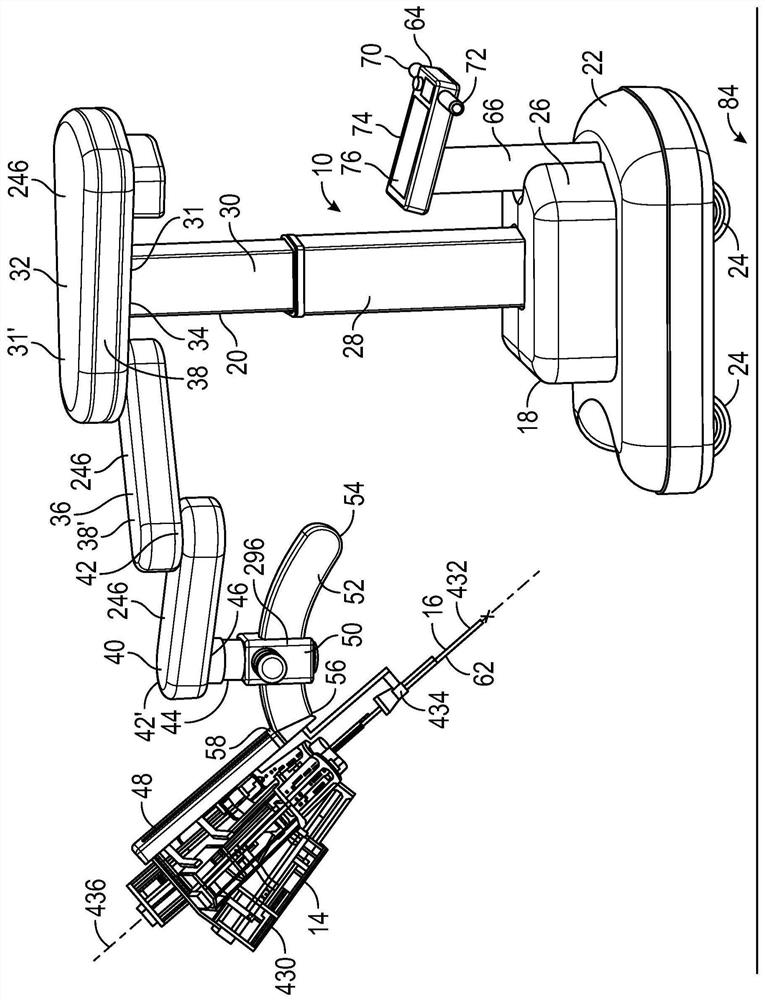
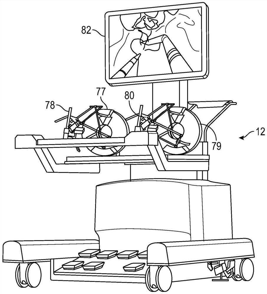
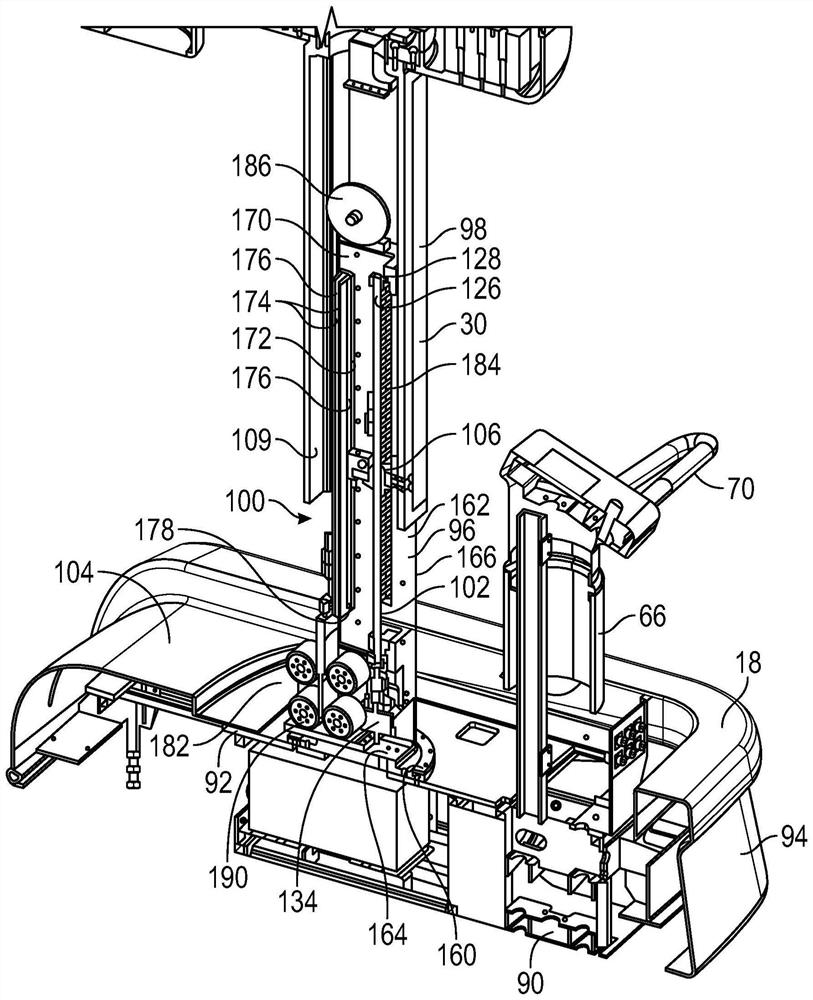
[0023] First refer to figure 1 and figure 2 , showing the instrument cart 10 ( figure 1 ) and console 12 ( figure 2 ). The instrument cart 10 herein is configured to allow for incision locations 16 (eg, mammals including humans) relative to a patient. figure 1 Position X) in locates the instrument controller 14 suspended from the instrument cart. The instrument cart 10 generally includes a cart base 18 and a positioning portion 20 extending upwardly from and supported on the cart base 18 . The cart base 18 is configured to roughly position the instrument controller 14 adjacent the patient and its incision location 16 . It includes: a base mount 22 supported on a plurality of rotatable wheels 24 (four, only two of which are shown), allowing the base mount to move along the ground 84; a drive portion 26, which positions the drive portion Above and above the base mount 22; and a tubular receiver 28 extending upwardly from the drive portion 26 within which the lift tube 30...


PUM


Abstract

An instrument cart configured to position an instrument controller at a desired position and attitude pitch relative to an incision position of a patient, the instrument cart comprising: a base; a lifting member movable relative to the base; a first planar translating member connected to the lifting member and arcuately movable relative to the lifting member; a second planar translating member connected to the first planar translating member and arcuately movable relative to the first planar translating member; a third planar translating member connected to the second planar translating member and arcuately movable relative to the second planar translating member; an arcuate slider base connected to the third planar translating member and movable relative to the third planar translating member; and an arcuate slider coupled to the arcuate slider base and movable relative to the arcuate slider base; and an instrument controller link connected to the arcuate sliding member, an instrument controller connected to the instrument controller link and movable relative to the instrument controller link.

Description

[0001] CROSS-REFERENCE TO RELATED APPLICATIONS [0002] This application claims the benefit of US Provisional Application Serial No. 62 / 914,226, filed October 11, 2019, which is hereby incorporated by reference in its entirety. technical field [0003] This specification relates to robotic surgical systems and procedures for minimally invasive surgery. More specifically, the present specification relates to the field of positioning devices for minimally invasive surgery. Background technique [0004] Non-invasive or non-highly invasive surgical techniques have been developed using tubular members to position cameras, surgical tools such as grippers, cutting elements, sutures, etc. A large incision is made in a patient's skin to examine or perform surgery on an internal body part. In these techniques, the distal end or distal end of a tubular device is guided through the anatomy using a series of cables configured to selectively bend the distal end of the tubular device wit...

Claims


Application Information

Patent Timeline
IPC IPC(8): A61B34/30A61B34/00A61B50/13
CPCA61B50/13A61B34/30A61B34/37A61B2034/742A61B2034/302A61B90/50A61B34/70
Inventor D·H·金申东石张泰虎朴镕晚李制翰南基勋申龙撤
Owner ENDOQUEST ROBOTICS INC
Learn More