Movable split-level combined surgical instrument trolley

A surgical instrument, mobile technology, applied in the direction of surgery, medical science, surgical equipment, etc., can solve the problems of surgical instrument cart shaking, pulley friction movement, loose fixation, etc., to prevent loose fixation, increase frictional resistance, Avoid fixed unstable effects

Inactive Publication Date: 2021-11-19
林剑鹏
View PDF0 Cites 0 Cited by
  • Summary
  • Abstract
  • Description
  • Claims
  • Application Information

AI Technical Summary

Problems solved by technology

[0003] And the surgical instrument trolley has the function of moving, using circular pulleys to move, but the friction of the pulley on the aseptic and smooth floor is small, and the pulley and the floor are easy to slide after ...

Method used


Image

  • Movable split-level combined surgical instrument trolley
  • Movable split-level combined surgical instrument trolley
  • Movable split-level combined surgical instrument trolley

Examples


Embodiment 1

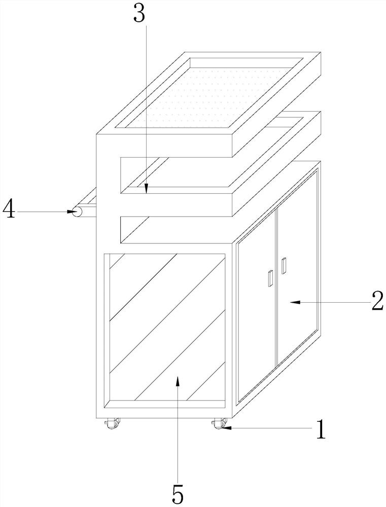
[0026] like Figure 1 - Figure 5 Below:

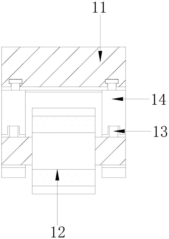
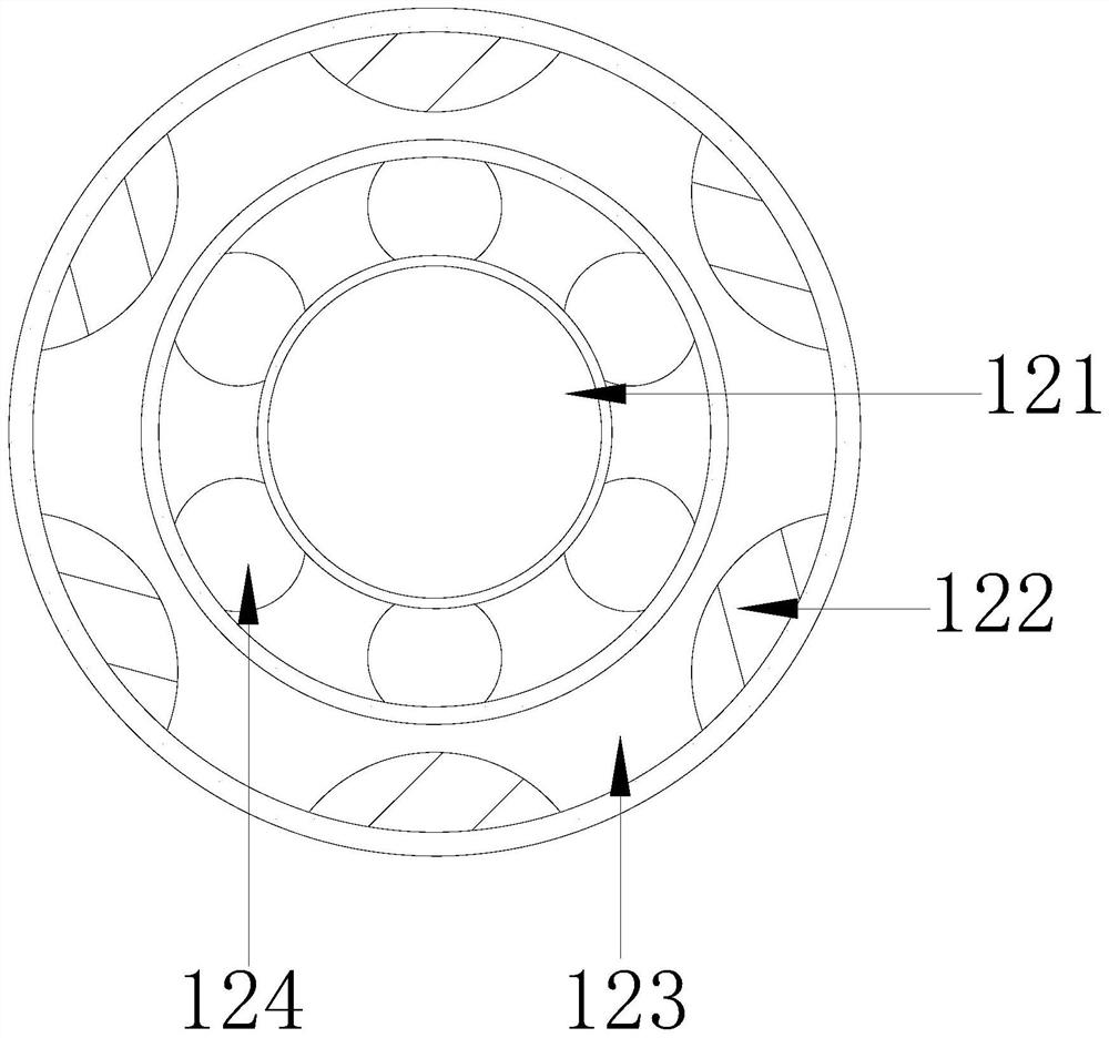
[0027] The present invention is a combination of split A mobile vehicle surgical instrument, which structure comprises a pulley mechanism, a storage cabinet 2, the disc 3 is placed, the push rod 4, the vehicle device 5, the push rod 4 embeded in the car left the instrument 5, the placement tray 3 is attached to the upper end of the vehicle instrument 5, the storage cabinet 2 located inside the instrument car 5, the upper end of the pulley mechanism 1 is welded to the lower end of the instrument car 5, the pulley mechanism 1 is provided with the fixing block 11, the rotatable structure 12 , the fixed structure 13, block 14 is rotated, the rotation of the side panel 13 at a lower end fixed block 11 is fixed, the fixing structure 13 is mounted inside the rotation block 14, the rotation of the intermediate structure 12 and the left and right sides of the upper end of the fixed structure 14 are block connected to a fixed block 11 is welded to th...

Embodiment 2

[0034] like Figure 6- Figure 8 Below:

[0035]Wherein, the fixing structure 13 is provided with a movable groove 131, a restricted plate 132, a friction structure 133, and the movable tank 131 is located on the upper end of the friction structure 133, the lower end of the restricted plate 132 and the upper end of the friction structure 133, and the The friction structure 133 is mounted inside the rotating block 14, and the fan-shaped angle of the movable tank 131 is 20 degrees, and the left side of the movable groove 131 is provided with a engagement block of the signaling limit plate 132, the restricted plate 132 inside the right side. A restricted spring is provided, and the limit plate 132 continuously produces a downward elastic force on the right side of the restricted plate 132, so that the friction structure 133 is engaged by the limit plate 132 limit activity in the movable tank 131, so that The rotational force of the friction structure 133 is converted into frictional re...


PUM


Abstract

The invention discloses a movable split-level combined surgical instrument trolley. The trolley structurally comprises a pulley mechanism, a storage cabinet, a placement disc, a push-pull rod and an instrument trolley, wherein the push-pull rod is fixedly embedded in the left side of the instrument trolley, the placement disc is installed at the upper end of the instrument trolley, the storage cabinet is located in the instrument trolley, and the upper end of the pulley mechanism is welded to the lower end of the instrument trolley. According to the invention, rotation of a rotating structure is blocked by pressing a fixed structure, the situation that the outer side of a connecting ring is in an uneven state due to shaking caused by unstable clamping of the rotating structure is avoided, and therefore, friction force to the ground is increased, the situation that a supporting ball is driven to rotate is avoided, and the situation that fixing and clamping are not firm is prevented; and therefore, a friction structure is clamped through limiting movement of a limiting plate in a movable groove, the rotating force of the friction structure is converted into friction resistance, the friction resistance to a compression plate is increased through a hollow groove, the situation of unstable fixing is avoided, the fixing resistance of the rotating structure is increased, and the situation of unstable fixing during stress is prevented.

Description

Technical field [0001] The present invention relates to surgical instruments, and in particular, to a combination of surgical instruments split mobile vehicle. Background technique [0002] The surgical instrument when the car is essential tool for surgery, the surgical tool for placement of a tray and a plurality of layers, the surgical instrument to prevent the vehicle sliding tray space generated, when taken directly access the surgical instrument. [0003] Less friction and effect movement of the surgical instrument having a car, using a circular pulleys move, but smooth pulley on sterile floor, and the floor slides easily between the pulleys in the force, the surgical instrument of the car is prone to shake case, so that the lower end of the surgical instrument drive pulley friction movement occurs, resulting in the case where fixing is not strong. Inventive content [0004] The present invention is achieved by the following technical solution: A mobile car split combinatio...

Claims


Application Information

Patent Timeline
IPC IPC(8): A61B50/13
CPCA61B50/13
Inventor 林剑鹏
Owner 林剑鹏
Why Eureka
Try Eureka