Plate arranging device

A sheet, structured technology for transport and packaging, conveyor items, etc.

Pending Publication Date: 2022-06-10
广州宁基智能系统有限公司
View PDF6 Cites 2 Cited by
  • Summary
  • Abstract
  • Description
  • Claims
  • Application Information

AI Technical Summary

Problems solved by technology

The disadvantage of this method is that it can only adjust the position of the front and back of the plate but not the left and right positions of the plate, so it has great limitations in application.

Method used


Image

  • Plate arranging device
  • Plate arranging device
  • Plate arranging device

Examples


Embodiment Construction

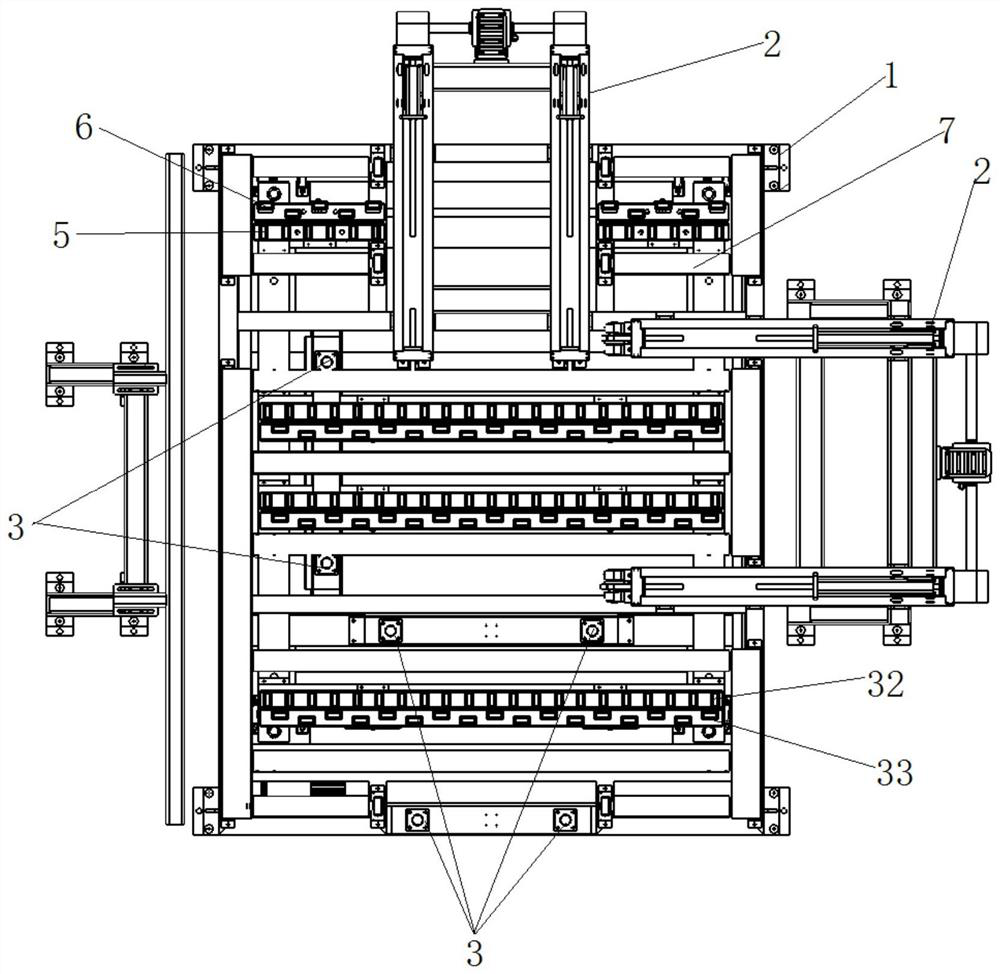
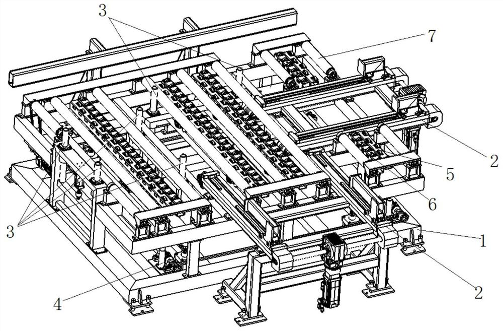
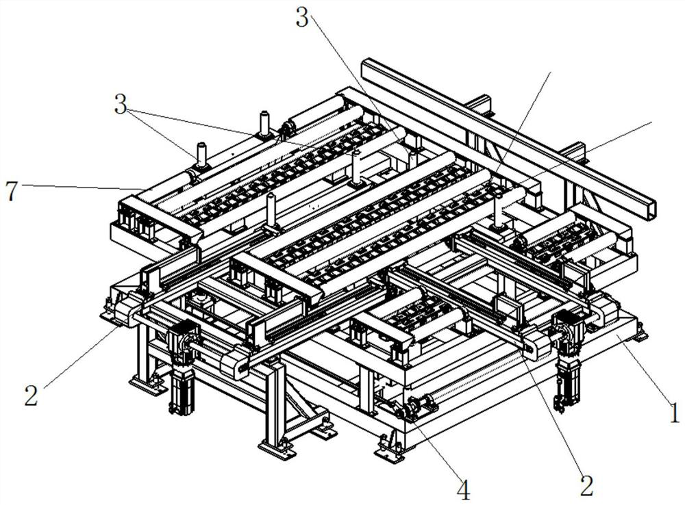
[0041] Further, it is necessary to automatically lower the ribs 3 of the regular frame. The specific process is as follows: the rib cylinder 28 stretches out, drives the rib connecting rod 25 to move downward, and the rib connecting rod 25 drives the rib retaining rod 24 to move on the rib bearing. 23 and move downwards, and the sidewall bar 24 moves downwards so as to be level with the level of the sidewall installation frame 22, and complete the descending action of the automatic sidewall.

[0042] Further, the action 4 of the conveying roller assembly conveys the sheet from the sheet regularizing device. The specific process is as follows: the motor 52 is started and connected through the transmission belt 53 to drive the movement of the conveying roller 51, and the transmission belt 52 installed between the conveying rollers 51 drives the adjacent The conveying roller 51 moves to convey the plate out of the plate regularizing device.

[0043] The basic principles, main fea...


PUM


Abstract

The plate tidying device comprises a rack, a fixed push plate assembly, a tidying frame automatic flange, a bidirectional conveying guide wheel assembly, a bidirectional conveying guide wheel assembly synchronous jacking mechanism, a transverse guide wheel assembly, a longitudinal guide wheel assembly and a conveying roller assembly. The machine frame is installed on the ground and serves as the reference of the plate tidying device, the conveying roller assembly is installed over the machine frame through a metal frame, a plurality of tidying frame automatic flanges are further arranged on the machine frame, and the two-way conveying guide wheel assembly synchronous jacking mechanism is arranged in the middle of the same plane of the machine frame. A transverse guide wheel assembly and a longitudinal guide wheel assembly are installed on the two-way conveying guide wheel assembly synchronous jacking mechanism, and the transverse guide wheel assembly and the longitudinal guide wheel assembly are arranged in the neutral position of the conveying roller assembly and located on the same plane with the conveying roller assembly.

Description

technical field [0001] The invention relates to a plate conveying device, in particular to a plate regularizing device. Background technique [0002] The transportation of the assembly line is an indispensable process in the automatic woodworking board processing and production. After each process is completed, the board needs to be transported to the processing equipment in the next link through the assembly line. In each link, due to the conveying equipment The own error of the board will cause the plate conveying position error to accumulate with the increase of conveying distance. If the accumulated error is too large, it will lead to incorrect processing position or processing failure due to errors during the transportation and processing of the plate. The location of the hole is not accurate; The general solution is to sense the position of the plate through the optical sensor that is facing the plate during the conveying process. Specifically, a special section of ...

Claims


Application Information

Patent Timeline
Patent Type & Authority Applications(China)
IPC IPC(8): B65G47/244
CPCB65G47/244
Inventor 柯建生张挺
Owner 广州宁基智能系统有限公司
Why Eureka
Try Eureka