Self-diversion gas pipeline plugging device

A technology for gas pipelines and occluders, which is applied in the directions of pipe components, pipes/pipe joints/pipes, mechanical equipment, etc., and can solve the problems of blockage failure, easy sticking, and increased control difficulty.

Inactive Publication Date: 2022-06-17
北京天兴燃气工程有限公司
View PDF10 Cites 1 Cited by
  • Summary
  • Abstract
  • Description
  • Claims
  • Application Information

AI Technical Summary

Problems solved by technology

At present, the plugging machine used in this field mainly uses the expansion cylinder to block the gas pipeline, which has the following problems: it is necessary to open equal-diameter holes, otherwise the plugging cannot be achieved, and the difficulty and workload of opening equal-diameter holes are relatively large; The expansion cylinder has high requirements on the matching degree of the equal-diameter holes, and the sealing is often not tight
In order to solve the existing problems of the expansion cylinder, those skilled in the art have developed an ex

Method used


Image

  • Self-diversion gas pipeline plugging device
  • Self-diversion gas pipeline plugging device
  • Self-diversion gas pipeline plugging device

Examples


Example Embodiment

[0037]首先需要说明的,本发明中所述的上、下、左、右、前、后等方位词只是根据附图进行的描述,以便于理解,并非对本发明的技术方案及请求保护范围进行的限制。

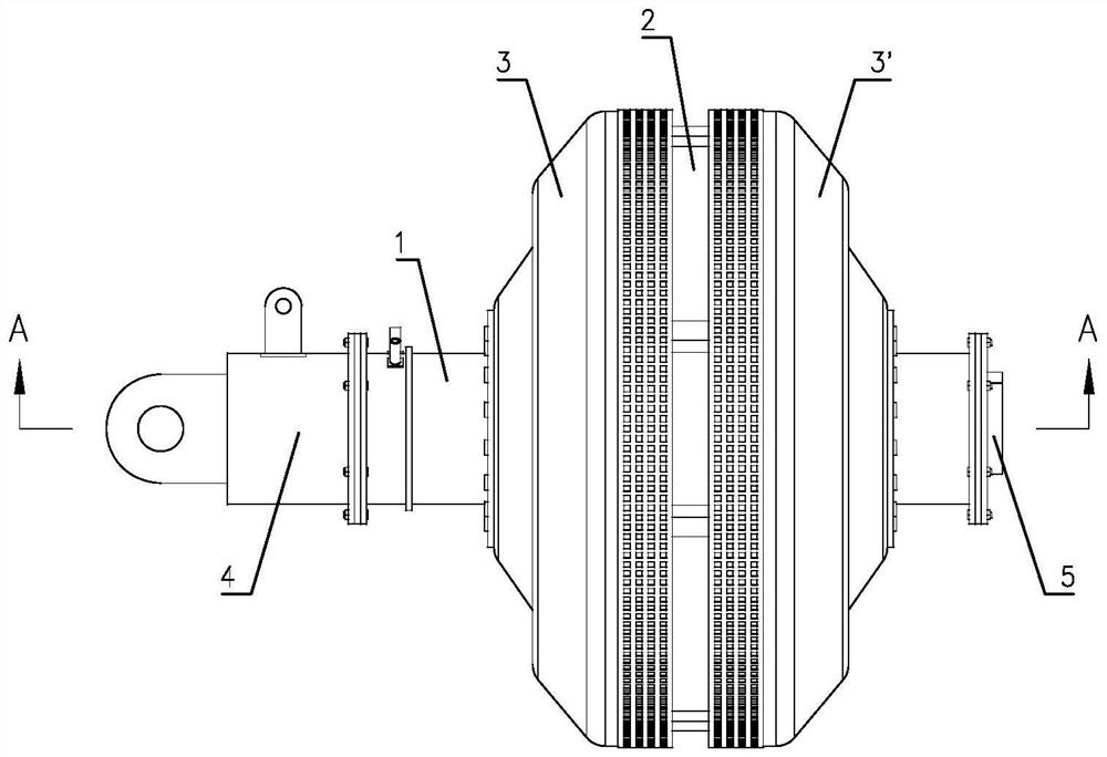
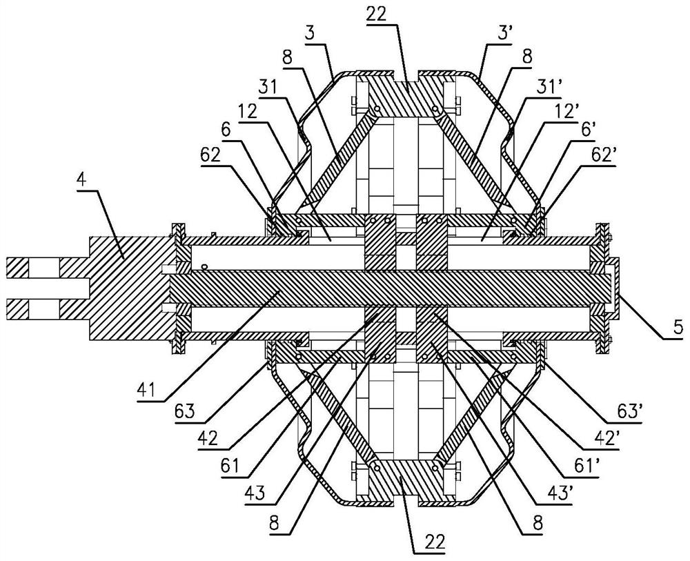
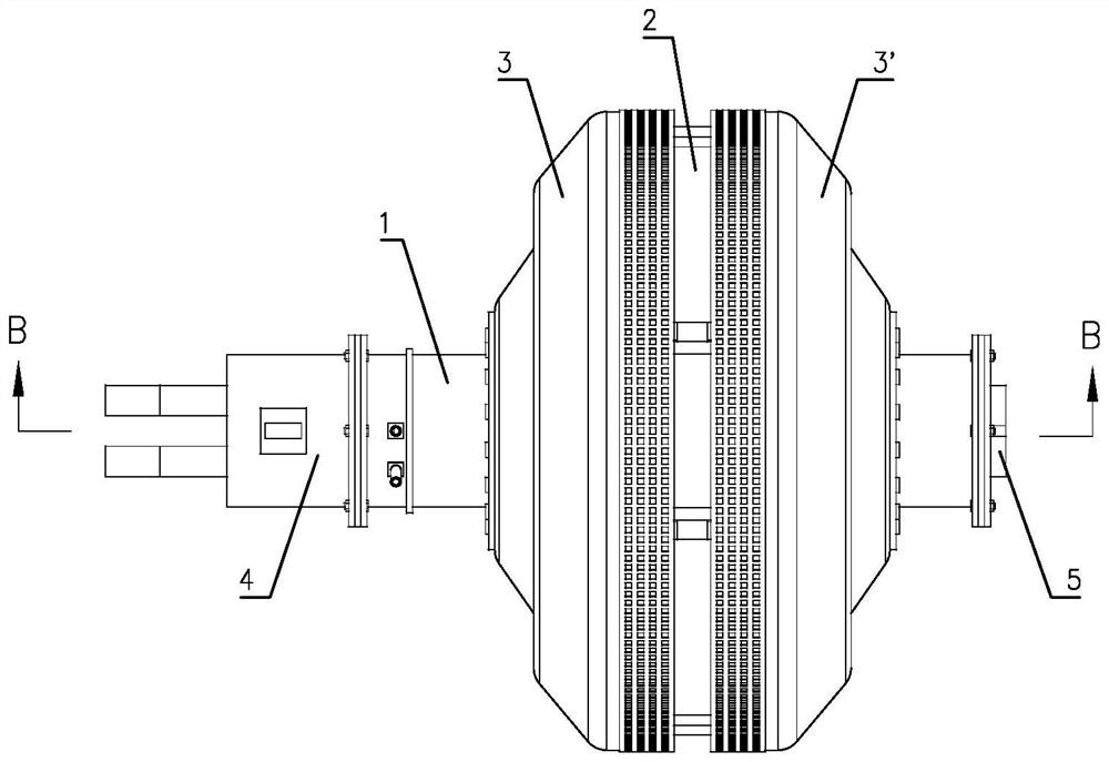
[0038]如图1至图20所示本发明一种自导流燃气管道封堵器的具体实施方式,包括支撑杆1、膨胀环2、左密封罩3和右密封罩3’。使支撑杆1采用管状结构并在其左右端对应密封固定电机4和封堵盘5,在支撑杆1上套设左滑环6和右滑环6’,在左滑环6和右滑环6’与支撑杆1之间设置密封结构,在支撑杆1中设置连接电机4的传动机构,让传动机构驱使左滑环6和右滑环6’反向滑动,在支撑杆1中设置导流管7,让导流管7的左端与支撑杆1上的第一管接头11连接,让导流管7的右端穿过封堵盘5并使两者密封配合。使膨胀环2采用由交替分布的第一弧形件21和第二弧形件22组合构成的结构,其中,第一弧形件21的两端设有向内倾斜且呈对称分布的导向面,导向面上设有滑槽211,滑槽211的两侧壁上设有导向孔212,相邻第一弧形件21上的导向孔212呈八字型,第二弧形件22的中部通过对称分布的连杆8分别与左滑环6和右滑环6’铰接,第二弧形件22的两端设有与滑槽211配合的滑块221,滑块221的两侧设有处于导向孔212中的导向柱222。让左密封罩3的左端与左滑环6密封固定连接,将左密封罩3的右端套在膨胀环2上并与第一弧形件21固定连接;让右密封罩3’的右端与右滑环6’密封固定连接,将右密封罩3’的左端套在膨胀环2上并与第一弧形件21固定连接。

[0039]通过以上结构设置就构成了一种基于电驱动的自导流双密封燃气管道封堵器。在实际应用中,首先通过电机4和传动机构使左滑环6和右滑环6’向两侧滑动,以使膨胀环2、左密封罩3和右密封罩3’处于收缩状态,然后将封堵器从开孔处置入燃气管道,接着通过电机4和传动机构使左滑环6和右滑环6’向中间滑动,当膨胀环2撑开到位后即可将左密封罩3和右密封罩3’紧密挤压在燃气管道内壁上,从而实现封堵目的。本发明通过在支撑杆1中设置导流管7,实现了自导流,封堵时使第一管接头11连接软管及有关检测仪表(压力表等),一方面可对燃气管道进行取压,提高了检测和控制的精确性,另一方面在需要时可对燃气进行放散,提高了安全性;通过使膨胀环2设置交替分布的第一弧形件21和第二弧形件22,并使相邻第一弧形件21上的导向孔212形成八字型,在滑块221与滑槽...


PUM


Abstract

The invention relates to a self-diversion gas pipeline plugging device which comprises a supporting rod, an expansion ring, a left sealing cover and a right sealing cover, a motor and a plugging disc are correspondingly fixed to the two ends of the supporting rod, a left sliding ring and a right sliding ring are arranged on the supporting rod, a transmission mechanism and a diversion pipe are arranged in the supporting rod, and the transmission mechanism enables the left sliding ring and the right sliding ring to slide reversely; the expansion ring is composed of first arc-shaped pieces and second arc-shaped pieces which are distributed alternately, guide faces are arranged at the two ends of each first arc-shaped piece, sliding grooves are formed in the guide faces, guide holes are formed in the side walls of the sliding grooves, the guide holes in the adjacent first arc-shaped pieces are in a splayed shape, and the second arc-shaped pieces are hinged to the left sliding ring and the right sliding ring through symmetrically-distributed connecting rods. Sliding blocks matched with the sliding grooves are arranged at the two ends of the second arc-shaped piece, guide columns located in the guide holes are arranged on the two sides of the sliding blocks, the two ends of the left sealing cover are correspondingly connected with the left sliding ring and the expansion ring, and the two ends of the right sealing cover are correspondingly connected with the right sliding ring and the expansion ring. The device has the advantages of compact structure, sensitive action and reliable plugging.

Description

technical field [0001] The invention relates to pipeline sealing technology, in particular to a self-guiding gas pipeline sealing device used for opening and sealing operations. Background technique [0002] In the process of connection, cutting and rerouting of the gas pipeline network, it is often necessary to perform hole sealing operations. At present, the plugging machine used in this field mainly uses the expansion cylinder to block the gas pipeline, which has the following problems: it is necessary to open equal-diameter holes, otherwise the plugging cannot be achieved, and the difficulty and workload of opening equal-diameter holes are relatively large; The expansion cylinder has high requirements on the matching degree of the equal-diameter holes, and the sealing is often not tight. In order to solve the existing problems of the expansion cylinder, those skilled in the art have developed an expandable ring-type pipeline occluder, such as the patent application whos...

Claims


Application Information

Patent Timeline
IPC IPC(8): F16L55/12F16L55/124F16L55/07
CPCF16L55/12F16L55/124F16L55/07
Inventor 付凯史福海郭常政李栋李清林王佰祥
Owner 北京天兴燃气工程有限公司
Why Eureka
Try Eureka