Double-seal pipeline plugging device

A double-seal and occluder technology, which is applied in the direction of pipe components, pipes/pipe joints/fittings, mechanical equipment, etc., can solve the problems of difficulty and heavy workload, prone to sticking, plugging failure, etc., and achieves a compact structure , strong adaptability and sensitive action

Active Publication Date: 2022-05-24
BEIJING GAS GRP
View PDF6 Cites 0 Cited by
  • Summary
  • Abstract
  • Description
  • Claims
  • Application Information

AI Technical Summary

Problems solved by technology

At present, the plugging machine used in this field mainly uses the expansion cylinder to seal the pipeline, which has the following problems: it is necessary to open equal-diameter holes, otherwise the plugging cannot be performed, and the difficulty and workload of opening equal-diameter holes are relatively large; The requirements for the matching degree of the equal-diameter holes are relatively high, and the sealing is often not strict
In order to solve the existing problems of the expansion cylinder, those skilled in the art have developed an expandable ring-type pipeline occluder, such as the patent application whose publication number is CN212929169U. Although the disclosed pipeline occluder can solve the existing problems of the expansion cylinder, its own There are the following defects: 1. Limited by its own structure, it is prone to plugging failure; 2. It needs to be driven by external power, which increases the difficulty of control; 3. It is easy to get stuck due to unbalanced force, and the sensitivity and poor adaptability

Method used


Image

  • Double-seal pipeline plugging device
  • Double-seal pipeline plugging device
  • Double-seal pipeline plugging device

Examples


Embodiment Construction

[0037] First of all, it should be noted that the orientation words such as upper, lower, left, right, front and rear described in the present invention are only descriptions according to the accompanying drawings, so as to facilitate understanding and do not limit the technical solutions of the present invention and the claimed protection scope. .

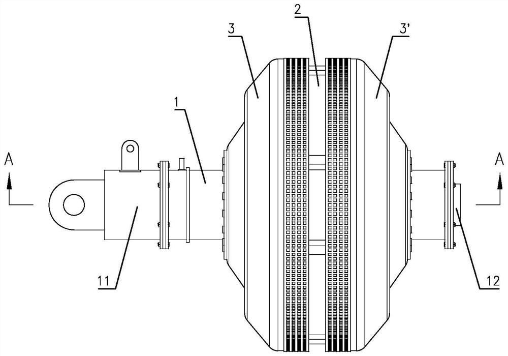
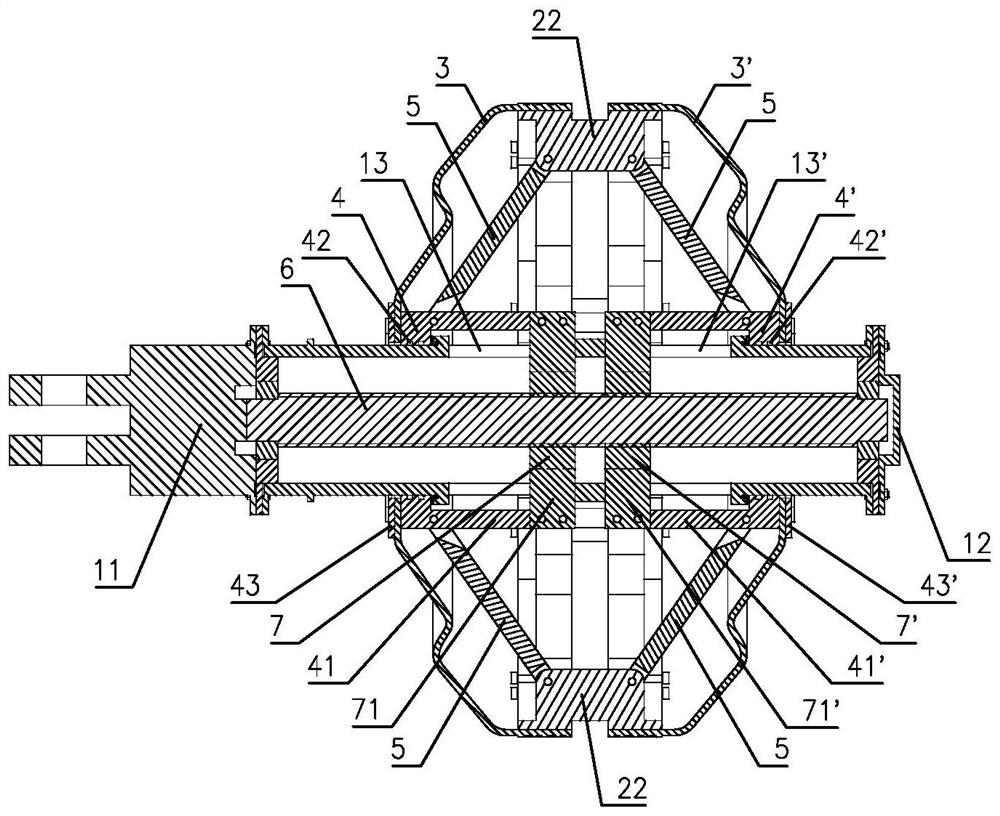
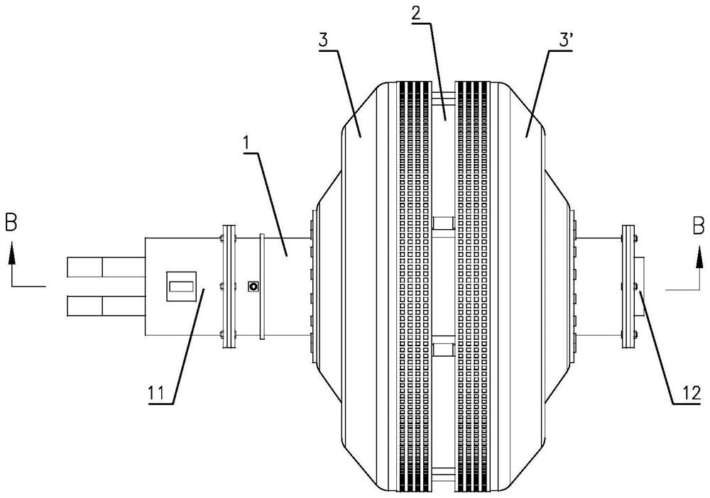
[0038] like Figure 1 to Figure 20The specific embodiment of a double-sealing pipeline occluder of the present invention is shown, including a support rod 1, an expansion ring 2, a left sealing cover 3 and a right sealing cover 3'. The support rod 1 adopts a tubular structure, the left and right ends of the support rod 1 are correspondingly sealed and fixed to the motor 11 and the blocking plate 12, the left slip ring 4 and the right slip ring 4' are sleeved on the support rod 1, and the left slip ring 4 and A sliding seal structure is arranged between the right slip ring 4' and the support rod 1, and a transmission mechanism conn...


PUM


Abstract

The double-sealing pipeline plugging device comprises a supporting rod, an expansion ring, a left sealing cover and a right sealing cover, a motor is arranged at the left end of the supporting rod, a left sliding ring and a right sliding ring are arranged on the supporting rod, a transmission mechanism connected with the left sliding ring and the right sliding ring is arranged in the supporting rod, and the expansion ring is composed of first arc-shaped pieces and second arc-shaped pieces which are alternately distributed; guide faces are arranged at the two ends of the first arc-shaped piece, sliding grooves are formed in the guide faces, guide holes are formed in the two side walls of the sliding grooves, the second arc-shaped piece is provided with supporting lugs, the supporting lugs are hinged to the left sliding ring and the right sliding ring through connecting rods respectively, the second arc-shaped piece is provided with sliding blocks matched with the sliding grooves, and guide columns located in the guide holes are arranged on the two sides of the sliding blocks. The left end of the left sealing cover is connected with the left sliding ring, the right end of the left sealing cover is sleeved on the expansion ring and connected with the first arc-shaped piece, the right end of the right sealing cover is connected with the right sliding ring, and the left end of the right sealing cover is sleeved on the expansion ring and connected with the first arc-shaped piece. The device has the advantages of compact structure, sensitive action and reliable plugging.

Description

technical field [0001] The invention relates to a pipeline plugging technology, in particular to a double-sealing pipeline plugging device for plugging openings of gas pipelines. Background technique [0002] In the process of connecting, cutting, and rerouting the gas pipeline network, it is often necessary to perform opening and blocking operations. At present, the plugging machine used in this field mainly uses the expansion cylinder to plug the pipeline, which has the following problems: it is necessary to open equal-diameter holes, otherwise the plugging cannot be performed, and the difficulty and workload of opening the equal-diameter holes are relatively large; the expansion cylinder The matching degree of the equal diameter holes is relatively high, and the sealing is often not strict. In order to solve the problems existing in the expansion cylinder, those skilled in the art have developed an expansion ring type pipeline occluder, such as the patent application wit...

Claims


Application Information

Patent Timeline
Patent Type & Authority Applications(China)
IPC IPC(8): F16L55/11
CPCF16L55/11
Inventor 祁丽荣左熠许彤杜燕凤田晓江高佳伟曹国权苏峥高观玲
Owner BEIJING GAS GRP
Why Eureka
Try Eureka