Automatic feeding and discharging mechanism for production line

A production line and lifting mechanism technology, applied to conveyors, mechanical conveyors, conveyor objects, etc., can solve the problems of high labor intensity and low efficiency, and achieve the effect of improving production efficiency

Pending Publication Date: 2022-06-21
苏州齐物智能装备有限公司
0 Cites 0 Cited by

AI-Extracted Technical Summary

Problems solved by technology

[0002] In the process of product manufacturing, products or materials between different processes or processes will be loaded onto pallets or removed from pallets. For example, for the lithium battery manufacturing industry, in different processes of li...

Abstract

The invention relates to an automatic feeding and discharging mechanism for a production line. The feeding and discharging mechanism comprises a frame body, a first tray conveying assembly, a tray transverse transplanting mechanism, a grabbing feeding and discharging assembly and a second tray conveying assembly. The first tray conveying assembly is used for conveying trays; the two ends of the tray transverse transplanting mechanism correspond to the first tray conveying assembly and the second tray conveying assembly correspondingly, and the tray transverse transplanting mechanism is used for transplanting trays to the corresponding positions of the grabbing, feeding and discharging assembly. The trays which are loaded and/or unloaded by the grabbing loading and unloading assembly are transplanted to the first tray conveying assembly or the second tray conveying assembly; and the second tray conveying assembly is used for conveying the trays. Automatic feeding and discharging are achieved, products or materials can be discharged to trays, or the products or the materials in the trays can be fed to other working procedures or stations of a production line, meanwhile, automatic input and output operation of full trays and empty trays is achieved, the production efficiency is remarkably improved, and the automatic feeding and discharging device is suitable for the requirement of intelligent manufacturing.

Application Domain

Loading/unloadingConveyor parts +1

Technology Topic

Process engineeringAutonomation +3

Image

  • Automatic feeding and discharging mechanism for production line
  • Automatic feeding and discharging mechanism for production line
  • Automatic feeding and discharging mechanism for production line

Examples

  • Experimental program(1)

Example Embodiment

[0026] Example:
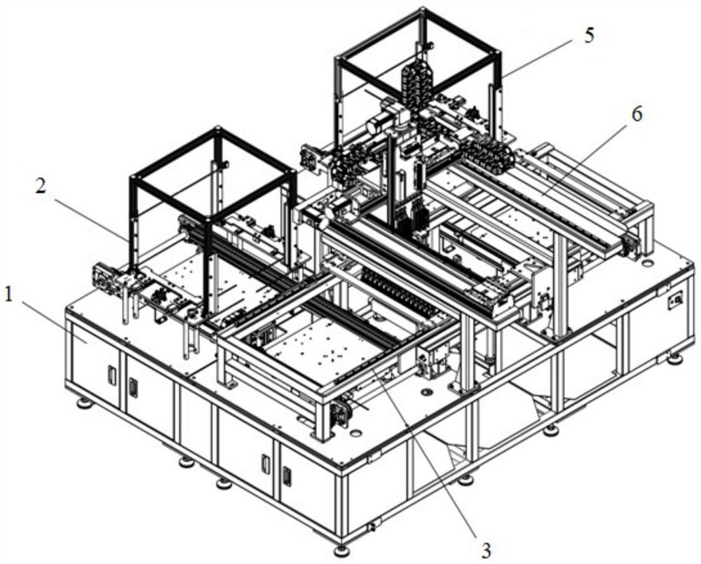
[0027] An automatic loading and unloading mechanism for a production line, which is characterized in that it includes: a frame body 1, a first tray conveying assembly 2, a tray lateral transplanting mechanism 3, a grabbing and unloading assembly 6, and a second tray conveying assembly 5; a first tray The conveying assembly is used for conveying the tray; the two ends of the lateral transplanting mechanism of the tray are respectively corresponding to the first tray conveying assembly and the second tray conveying assembly, and are used for transplanting the tray to the grabbing and unloading material The components correspond to the positions, and the pallets that are loaded and/or unloaded by grabbing the loading and unloading components are transplanted to the first or second pallet conveying components; the second pallet conveying component is used for pallet conveying.
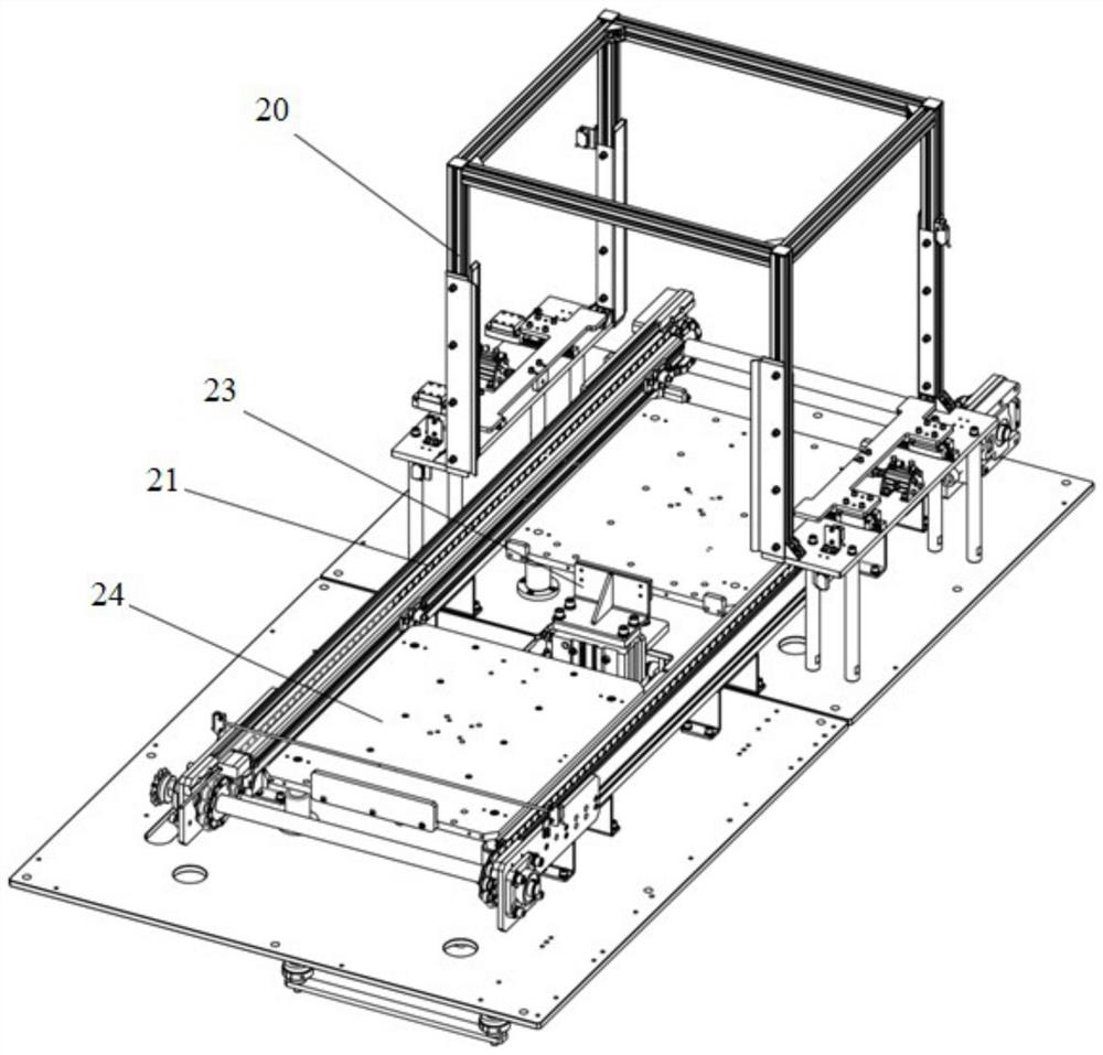
[0028] The first pallet conveying assembly or the second pallet conveying assembly includes: a pallet conveying unstacking mechanism 20 and a pallet conveying traverse line; Line transfer blocking mechanism 23, pallet conveying traverse line lifting mechanism 24; the pallet conveying unstacking mechanism and the pallet conveying traverse line lifting mechanism are respectively arranged at both ends of the pallet conveying traverse line body position; the first pallet conveying assembly, the pallet conveying traverse line blocking mechanism is set at a position between the pallet conveying unstacking tray mechanism and the pallet conveying traverse line lifting mechanism; the second pallet a conveying assembly, wherein the pallet conveying traverse line blocking mechanism is arranged at the position of one end of the pallet conveying traverse line body and one end of the pallet conveying unstacking plate mechanism;
[0029] The pallet conveying and disassembling mechanism includes: disassembling plate frame 201, disassembling plate lifting cylinder 202, disassembling plate lifting fixing ring 203, disassembling plate lifting guide rod 204, disassembling plate lifting linear bearing 205 , Unstacking tray lifting fixing plate 206, Unstacking tray lifting bottom plate 207, Unstacking tray unstacking piece 208, Unstacking tray unstacking joint 209, Unstacking tray unstacking cylinder 210, Unstacking tray unstacking fixing member 211 , the unstacking disk slider 212, the unstacking disk slide rail 213, and the unstacking disk support column 214; the unstacking disk lifting linear bearing is arranged on the unstacking disk lifting fixing plate, and the unstacking disk lifts The guide rod is sleeved on the lifting linear bearing of the unstacking plate, and is respectively connected with the lifting fixing ring of the unstacking plate and the lifting bottom plate of the unstacking plate; the lifting cylinder of the unstacking plate is connected with the The stacking tray lifting bottom plate is driven and connected, and the destacking tray lifting bottom plate is driven to perform a lifting movement by the destacking tray lifting cylinder; the destacking tray support column is arranged on the destacking tray lifting fixing plate , the unstacking tray unstacking fixing member is connected on the unstacking tray support column; the unstacking tray unstacking cylinder and the unstacking tray slide rail are arranged on the unstacking tray unstacking fixing member the unstacking disc slider is connected with the unstacking disc unstacking piece, and the unstacking disc slider is slidably connected with the unstacking disc slide rail; the unstacking disc unstacking cylinder passes through the unstacking disc The disc destacking joint is drivingly connected with the destacking disc destacking piece; the destacking disc destacking piece is driven by the destacking disc destacking cylinder, and the destacking disc lifting base plate is driven by the destacking disc lifting cylinder to cooperate to realize the destacking disc action, the stacked pallets are split to the pallet conveying traverse line, or the pallets conveyed by the pallet conveying traverse line are stacked; stopper 216;
[0030] The pallet conveying traverse line blocking mechanism realizes the blocking action by driving the blocking block through the cylinder;
[0031] The pallet conveying traverse line body includes: traverse line frame body 221, drive motor 222, drive chain 223, drive sprocket 224, code scanner 225, double-speed chain drive shaft 226, double-speed sprocket 227, double-speed chain support Wheel 228, traverse line double-speed chain 229, double-speed chain driven shaft 230; the drive motor drives the drive chain and drive sprocket to move, thereby driving the double-speed chain drive shaft, double-speed chain driven shaft, double-speed sprocket, traverse line double-speed chain movement; the double-speed chain supporting wheel is arranged on the lower side of the traverse line double-speed chain; a code scanner is used for pallet scanning; the traverse line frame body is provided with a traverse line check member 231; The traverse line-to-radiation sensor 232 is arranged on the traverse line frame body;
[0032] The pallet conveying traverse line lifting mechanism is arranged on the lower side of one end of the pallet conveying traverse line body; the pallet conveying traverse line lifting mechanism includes: Conveying traverse line lifting joint 242, pallet conveying traverse line lifting linear bearing 243, pallet conveying traverse line lifting fixing plate 244, pallet conveying traverse line lifting cylinder 245, pallet conveying traverse line lifting guide rod 246. Pallet conveying traverse line lifting guide rod fixing ring 247; the pallet conveying traverse line lifting linear bearing is arranged on the pallet conveying traverse line lifting fixing plate; the pallet conveying traverse line lifting The guide rod is penetrated through the linear bearing of the pallet conveying traverse line lifting, and is respectively connected with the pallet conveying traverse line lifting bottom plate and the fixing ring of the pallet conveying traverse line lifting guide rod; the pallet conveying The traverse line lifting cylinder is drivingly connected with the pallet conveying traverse line lifting base plate through the pallet conveying traverse line lifting joint; The lifting motion is used to lift the tray on the tray conveying line body, and wait for the tray to be transplanted by the lateral transplanting mechanism of the tray; on the line body.
[0033] The tray lateral transplanting mechanism includes: tray lateral transplanting mechanism bracket 30, tray lateral transplanting slide rail 31, tray lateral transplanting slider 32, tray lateral transplanting member 33, tray lateral transplanting cylinder block 34, tray lateral transplanting Transplanting cylinder 35, loading and unloading grasping and lifting positioning cylinder 36, loading and unloading grasping and lifting positioning member 37, pallet transplanting clamping cylinder 38, pallet transplanting clamping bracket 39, loading and unloading grasping and lifting mechanism 40 ; the tray lateral transplanting cylinder is arranged on the tray lateral transplanting mechanism bracket, the tray lateral transplanting cylinder base is connected with the tray lateral transplanting member, and the tray lateral transplanting member is provided with the tray on the lower side The lateral transplanting slider, the tray lateral transplanting sliding rail is set on the upper side of the tray lateral transplanting mechanism bracket, the tray lateral transplanting slider is slidably connected with the tray lateral transplanting slide rail, and the tray lateral transplanting slide rail is slidably connected, and the tray lateral transplanting slide rail is moved laterally through the tray The planting cylinder drives the tray lateral transplanting cylinder base to drive the tray lateral transplanting member to move; the tray transplanting clamping cylinder is arranged on the tray lateral transplanting member, and drives the tray transplanting clamping bracket to realize the lateral movement of the tray. Movement to realize the tray transfer between the tray conveying assembly and the loading and unloading grasping and lifting mechanism. When the tray is transplanted from the loading and unloading grasping and lifting mechanism to the second tray transporting assembly, the first tray can be transported. The new tray on the component is transplanted to the loading and unloading grabbing and lifting mechanism, and at the same time, the automatic input and output operations of full and empty trays are realized, which effectively improves the work efficiency. Between the brackets of the lateral transplanting mechanism, it is used to drive the loading and unloading grasping and lifting positioning members to position the transplanted tray;
[0034]The loading and unloading grasping and lifting mechanism is arranged between the brackets of the lateral transplanting mechanism of the tray, and corresponds to the position of the grasping and unloading components; the loading and unloading grasping and lifting mechanism comprises: loading and unloading grasping and lifting Bottom plate 401, loading and unloading grasping and lifting joint 402, loading and unloading grasping and lifting linear bearing 403, loading and unloading grasping and lifting fixed plate 404, loading and unloading grasping and lifting cylinder 405, loading and unloading grasping and lifting guide shaft 406 , Loading and unloading grabbing and lifting fixing ring 407; The loading and unloading grabbing and lifting fixed plate is provided with a top plate blocking part 408 for loading and unloading grabbing; Switch 409; the loading and unloading grabbing and lifting linear bearing is worn on the loading and unloading grabbing and lifting fixing plate; the loading and unloading grabbing and lifting guide shaft is passed through the loading and unloading grabbing and lifting linear bearing are respectively connected with the loading and unloading grasping and lifting bottom plate and the loading and unloading grasping and lifting fixing ring; the loading and unloading grasping and lifting cylinder is connected with the loading and unloading grasping and lifting joint through the loading and unloading grasping and lifting joint Drive connection with the lifting bottom plate; drive the loading and unloading grasping and lifting bottom plate to carry out the lifting movement through the loading and unloading grasping and lifting cylinder, which is used to lift and lower the tray transplanted by the tray transplanting clamping bracket;
[0035] The grasping and unloading components include: a grasping and unloading X-axis motion module 52 , a grasping and unloading Y-axis motion module 53 , a grasping and unloading Z-axis motion module 54 , and a grasping and unloading jaw mechanism 50 , through the grabbing and unloading Y-axis motion module to drive the grabbing and unloading X-axis motion module to move in the Y-axis direction, and the grabbing and unloading X-axis motion module drives the grabbing and unloading X-axis motion module The Z-axis motion module moves in the X-axis direction, and the grabbing and unloading jaw mechanism is driven by the grabbing and unloading Z-axis motion module to move in the Z-axis direction;
[0036] The grabbing and unloading X-axis motion module, the grabbing and unloading Y-axis motion module, and the grabbing and unloading Z-axis motion module can be driven by a cylinder or a motor to drive a synchronous belt or a lead screw;
[0037] The grasping and unloading clamping jaw mechanism includes: grasping and unloading Z-axis motion module connector 501, a cylinder air distribution module 502, a grasping and unloading clamping jaw lifting cylinder 503, and a grasping and unloading clamping jaw lifting mounting plate 504 , Grab the loading and unloading jaw lifting joint 505, grasp the top plate 506 of the loading and unloading jaw assembly, grasp the connecting plate 507 of the loading and unloading jaw assembly, grasp the loading and unloading jaw assembly 500, grasp the loading and unloading jaw lifting slide rail 508. Grasp the loading and unloading jaws to lift the slider 509; the grasping and unloading Z-axis motion module connector is connected with the grasping and unloading Z-axis motion module; the cylinder air distribution module is arranged on the Grab and unload the Z-axis motion module connector; the grasping and unloading jaw lifting mounting plate is connected with the grasping and unloading Z-axis motion module connector, and the grasping and unloading jaw lifting cylinder is connected to the The grabbing and unloading jaws are connected to the lifting and mounting plate, the grabbing and unloading jaws lifting slider is arranged on the grabbing and unloading jaws lifting and mounting plate, and the grabbing and unloading jaws lifting rails are connected to the lifting and mounting plate. The grasping and unloading clamping jaw lifting slides are slidably connected, and the grasping and unloading clamping jaw lifting slide rails are connected with the connecting plate of the grasping and unloading clamping jaw assembly, and the grasping and unloading clamping jaw assembly connecting plate The upper end is connected to the top plate of the grabbing and unloading jaw assembly, and the grabbing and unloading jaw lifting cylinder is connected to the top plate of the grabbing and unloading jaw assembly through the grabbing and unloading jaw lifting joint; the The grabbing and unloading jaw assembly is arranged on the lower side of the top plate of the grabbing and unloading jaw assembly and the side of the connecting plate of the grabbing and unloading jaw assembly; the grabbing and unloading jaw assembly includes: grabbing and unloading Gripper Cylinder Positioning Post 5001, Grab and Unload Claw Cylinder Positioning Spring 5002, Grab Unloading Claw Cylinder Block 5003, Grab Unloading Claw Cylinder 5004, Grab Unloading Claw 5005, Grab Unloading Clamp Claw cylinder slide rail 5006, grabbing and unloading clamping jaw cylinder slider 5007; the grabbing and unloading clamping jaw cylinder slide rail is arranged on the side of the connecting plate of the grabbing and unloading clamping jaw assembly, and the grabbing and unloading clamp The claw cylinder slide rail is slidably connected with the grabbing and unloading clamping jaw cylinder block, and the grabbing and unloading clamping jaw cylinder slider is connected with the grabbing and unloading clamping jaw cylinder block; the grabbing and unloading clamps One end of the claw cylinder positioning column is penetrated on the top plate of the grasping and unloading clamping claw assembly, and the other end is connected with the grasping and unloading clamping claw cylinder seat. A positioning spring for the grabbing and unloading jaws cylinder is arranged between the top plate of the grabbing and unloading jaw assembly and the grabbing jaws cylinder base, and the grabbing and unloading jaws cylinder is arranged on the grabbing up and down jaws. The underside of the cylinder base of the material gripper is driven to grasp the loading and unloading gripper to realize loading and unloading. Thus, the loading and/or unloading of the tray is completed by grabbing the loading and unloading assembly.

PUM

no PUM

Description & Claims & Application Information

We can also present the details of the Description, Claims and Application information to help users get a comprehensive understanding of the technical details of the patent, such as background art, summary of invention, brief description of drawings, description of embodiments, and other original content. On the other hand, users can also determine the specific scope of protection of the technology through the list of claims; as well as understand the changes in the life cycle of the technology with the presentation of the patent timeline. Login to view more.

Similar technology patents

Three-dimensional production system of prefabricated components

ActiveCN105773827AIncreased production flexibilityIncrease productivity
Owner:国新德

Method for preparing graphene efficiently

InactiveCN103058176AIncrease productivitylow cost
Owner:HUAQIAO UNIVERSITY +1

Spot welding machine

ActiveCN102114572AIncrease productivityGuarantee spot welding quality
Owner:NINGBO MINTH AUTOMOTIVE PARTS RES&DEV CO LTD

Classification and recommendation of technical efficacy words

Why Eureka
Try Eureka