
Longitudinal swinging method for air grid

A technology of opposing swinging and wind grids, applied in glass tempering, manufacturing tools, glass manufacturing equipment, etc., can solve the problems of serious wind spots, uneven wind exposure, uneven arrangement of air holes, etc., to improve the quality of tempering, The effect of uniform force and reduction of wind spots

Pending Publication Date: 2022-06-21
LUOYANG LANDGLASS TECH CO LTD
View PDF0 Cites 0 Cited by
  • Summary
  • Abstract
  • Description
  • Claims
  • Application Information

AI Technical Summary

Problems solved by technology

[0002] At present, in the process of glass tempering, in order to make the cooling of the hot glass in the air grid more uniform, the glass side is driven by the conveying roller table to swing back and forth along the glass conveying direction, while receiving the air cooling of the air grid, but the air grid is due to The wind pressure is high and concentrated, and the air holes are arranged unevenly. When the glass moves between the air grilles, the wind is uneven, resulting in serious wind spots, so that it is impossible to obtain high-quality tempered glass.

Method used


Image

  • Longitudinal swinging method for air grid

Examples


Embodiment 1

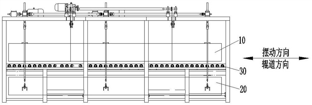
[0025] In this embodiment, the upper air grill 10 and the lower air grill 20 swing at a constant speed, and the swing rate is V=2mm / s or 15mm / s. In the description, the swing speed refers to the movement of the air grill between the two maximum swings. The speed does not include the speed change when the wind grill swings and turns, because when turning, there must be a process of speed reduction or increase. In this embodiment, the air grid first accelerates during a single swing, then at a constant speed, and finally decelerates. The process of acceleration and deceleration must exist, so the swing rate V=2mm / s or 15mm / s in this embodiment is Velocity in a uniform process. The swing range of the upper wind grille 10 and the lower wind grille 20 is fixed, and the swing range is D=10mm or 50mm. The speed U at which the conveying roller table 30 drives the glass to move is 40mm / s or 300mm / s. By controlling the swing rate and swing amplitude of the upper air grid 10 and the lo...

Embodiment 2

[0031] Embodiment five

Embodiment 3

In this embodiment, when the thickness of the glass is H=12mm, the upper air grid 10 and the lower air grid 20 swing at a constant speed, V=12mm / s, the frequency F of the upper air grid 10 and the lower air grid 20 is 1.5 circles / s, and the glass enters the upper air grid 10 and the blowing area of ​​the lower wind grill 20, the time T=170s or 210s for the swing of the upper wind grill 10 and the lower wind grill 20. The speed U at which the conveying roller table drives the glass movement is 170mm / s. In this embodiment, the thickness H of the glass is selected to be 12mm. According to the thickness of the glass, by controlling the swing frequency and swing time of the upper air grid 10 and the lower air grid 20, the time for the air outlet to stay on the glass surface can be controlled, and the conveying roller table can be controlled. The transmission rate, under this parameter, the glass can achieve a better cooling effect and reduce the occurrence of wind spots.

[0034] I...


PUM


Abstract

The invention provides an air grid longitudinal swing method which comprises the following steps: when heated glass advances or reciprocates on a conveying roller way in a cooling section along a glass conveying direction, a reciprocating swing mechanism enables an upper air grid and a lower air grid to swing along the glass conveying direction, and the upper air grid and the lower air grid swing in the same direction or swing in opposite directions; the upper air grid and the lower air grid are the same in swing speed and swing amplitude, and the upper air grid and the lower air grid are kept in synchronous steering. Glass is placed on the conveying roller way, the upper air grid and the lower air grid blow air to the glass on the conveying roller way, the upper air grid and the lower air grid swing in the glass conveying direction, the glass is placed on the conveying roller way to move, air outlet holes of the air grid A and the upper air grid and the lower air grid face different positions of the glass, and air spots are reduced.

Description

technical field [0001] The invention relates to the field of tempered glass manufacturing, in particular to a method for longitudinally swinging an air grid. Background technique [0002] At present, in the process of glass tempering, in order to make the cooling of the hot glass in the air grid more uniform, the glass side is driven by the conveying roller table to swing back and forth along the glass conveying direction, while receiving the air cooling of the air grid, but the air grid is due to The wind pressure is high and concentrated, and the air holes are unevenly arranged. When the glass moves between the air grilles, the wind is uneven, resulting in serious wind spots, so that it is impossible to obtain high-quality tempered glass. Contents of the invention [0003] Aiming at the problems existing in the prior art, the object of the present invention is to provide a method for longitudinally swinging the air grid, so as to reduce the appearance of wind spots and i...

Claims


Application Information

Patent Timeline
IPC IPC(8): C03B27/044C03B27/04
CPCC03B27/0404C03B27/044
Inventor 赵雁张克治张大鹏
Owner LUOYANG LANDGLASS TECH CO LTD
Learn More