Rainproof threshold structure of railway vehicle control cabin and railway vehicle

A railway vehicle and control room technology, which is applied in the rainproof threshold structure and the field of railway vehicles, to achieve the effects of avoiding corrosion of weld seams, reducing repairs and maintenance, and reducing deformation

Active Publication Date: 2022-06-24
CRRC TAIYUAN CO LTD
View PDF4 Cites 0 Cited by
  • Summary
  • Abstract
  • Description
  • Claims
  • Application Information

AI Technical Summary

Problems solved by technology

[0003] The purpose of the present invention is to address the deficiencies in the prior art, to provide a rain-proof threshold structure of a railway vehicle control room and a railway vehicle. The outer side of the door simplifies the structure while avoiding the deformation caused by rubber riveting or sealing defects caused by aging, and the threshold with a diversion part is used to divert the rainwater entering the inner side of the lower door frame. It can discharge all the diverted rainwater and protect the interior of the railway vehicle from rainwater

Method used


Image

  • Rainproof threshold structure of railway vehicle control cabin and railway vehicle
  • Rainproof threshold structure of railway vehicle control cabin and railway vehicle
  • Rainproof threshold structure of railway vehicle control cabin and railway vehicle

Examples


Embodiment 1

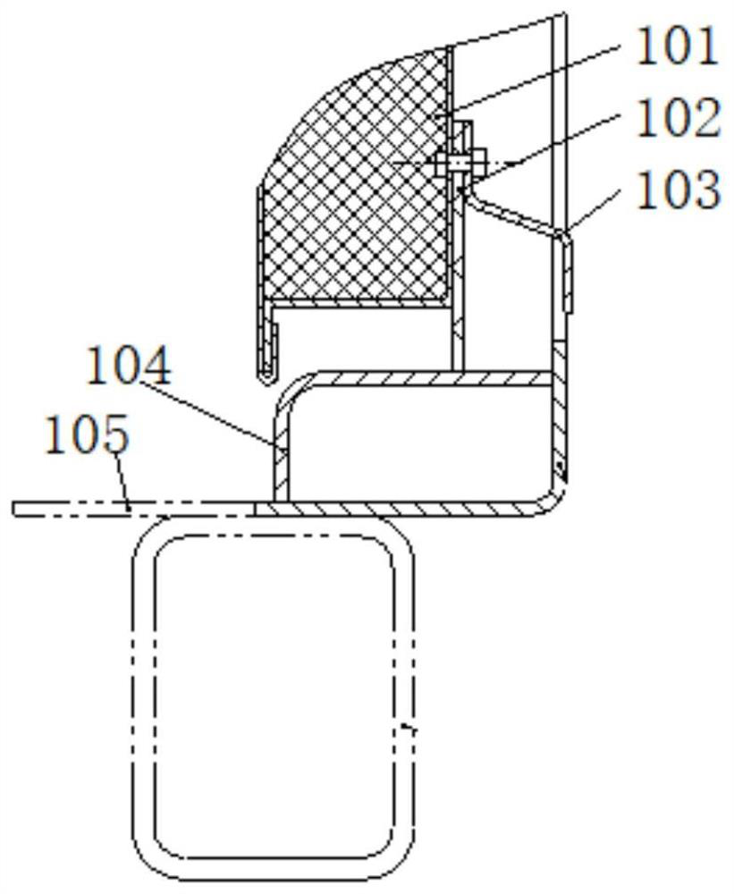
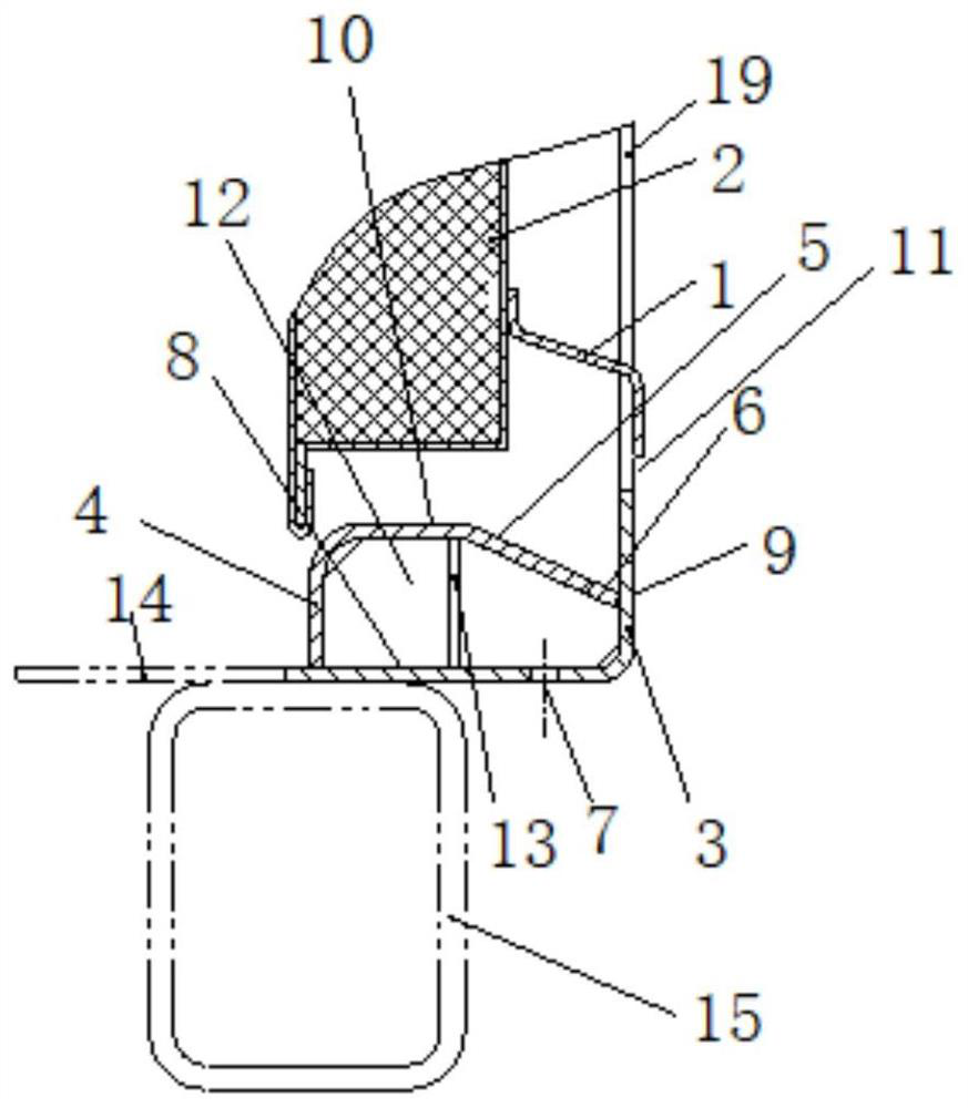
[0039] like Figure 2 to Figure 8 As shown, the present invention provides a rain-proof door sill structure of a railway vehicle operating room and a railway vehicle, the structure comprising:

[0040] Rain eaves 1, one end of the rain eaves 1 is connected to the outside of the control room door 2 of the railway vehicle, and the other end of the rain eaves 1 is inclined downward and extends to the outside of the lower door frame 3 of the control room door 2 of the railway vehicle;

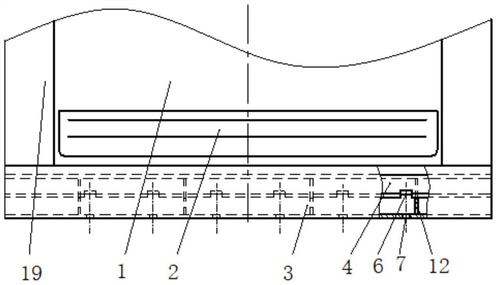
[0041] The door sill 4, the door sill 4 encloses a cavity on the inner side of the lower door frame 3, the door sill 4 includes a guide part 5, the guide part 5 is arranged at one end of the door sill 4 close to the lower door frame 3 and slopes downward, and the guide part 5 is close to the lower door frame 3 One end of the door is provided with a plurality of notches 6, and the bottom of the lower door frame 3 is provided with a drainage hole 7.

[0042] Specifically, the structure of the rain-p...

Embodiment 2

[0059] like Figure 9 and Figure 10 As shown, the difference between this embodiment and the first embodiment is:

[0060] In this embodiment, one end of the lower door frame 3 close to the interior of the railway vehicle is connected to the floor 14 of the railway vehicle, the lower side beam 15 of the railway vehicle is located below the lower door frame 3, and the drainage hole 7 is located on the inner side of the lower side beam 15; A first through hole 16 and a second through hole 17 are respectively opened on the top surface and the bottom surface of the beam along the vertical direction, and the first through hole 16 communicates with the drainage hole 7 .

[0061] Specifically, when the vertical part 9 of the lower door frame 3 of the operating room is aligned with or close to the outer side of the lower side beam, the lower measuring beam affects the drainage function of the drainage hole 7 . A corresponding number of first through holes 16 and second through hole...


PUM


Abstract

The invention discloses a rainproof doorsill structure of a control cabin of a railway vehicle and the railway vehicle, the rainproof doorsill structure comprises a rain eave, one end of the rain eave is connected to the outer side of a control cabin door of the railway vehicle, and the other end of the rain eave inclines downwards and extends towards the outer side of a lower doorframe of the control cabin door of the railway vehicle; a cavity is defined by the doorsill on the inner side of the lower door frame, the doorsill comprises a flow guide part, the flow guide part is arranged at the end, close to the lower door frame, of the doorsill and inclines downwards, a plurality of notches are formed in the end, close to the lower door frame, of the flow guide part, and drainage holes are formed in the bottom of the lower door frame; according to the rainproof doorsill structure, the structure of a rubber barrier strip is omitted, the rain eave is directly connected to the outer side of the control room door, the structure is simplified, meanwhile, the sealing defect caused by deformation or aging due to rubber riveting is avoided, the doorsill with the flow guide part is adopted to guide rainwater entering the inner side of the lower doorframe, and the rainproof effect is good. And the gaps and the drainage holes are formed, so that the guided rainwater can be completely drained, and the interior of the railway vehicle is protected against rainwater invasion.

Description

technical field [0001] The invention belongs to the technical field of railway vehicles, and more particularly, relates to a rain-proof threshold structure of a railway vehicle operating room and a railway vehicle. Background technique [0002] like figure 1 As shown in the figure, the door of the control room of the existing railway stone ballast hopper car adopts a single sealing structure of rubber strips, and the left and right and the upper part are sealed on three sides. , the sealing performance of this structure is poor, the rubber retaining strip 102 and the baffle 103 are not reliable against rain, and the rainwater is easy to fall along the outer door panel 101 or from the door seam to the threshold 104 to form a water accumulation area and enter the operation room, causing the floor inside the threshold 105 corrosion, such as serious corrosion of floor 105, will not only affect the safety of operators in the operating room, but also increase the workload of floo...

Claims


Application Information

Patent Timeline
Patent Type & Authority Applications(China)
IPC IPC(8): B61C17/04B61D19/00B61C17/00
CPCB61C17/04B61D19/001B61C17/00Y02T30/00
Inventor 李旭英袁太红吴春梅郭欢哈彩霞李云霞张莉吴佳张蓓庞秋燕冯凯刘文胜吴胜财
Owner CRRC TAIYUAN CO LTD
Why Eureka
Try Eureka