
Movable bulletproof wall

A bulletproof wall and bulletproof plate technology, which is applied to movable targets, offensive equipment, targets, etc., can solve the problems of low energy utilization and energy utilization, and achieve the effects of rapid cost reduction, simple maintenance and maintenance, and ingenious conception.

Pending Publication Date: 2022-06-24
福建泉城特种装备科技有限公司
View PDF0 Cites 0 Cited by
  • Summary
  • Abstract
  • Description
  • Claims
  • Application Information

AI Technical Summary

Problems solved by technology

[0004] The purpose of the present invention is to solve the problem of low energy utilization in traditional mobile bulletproof walls

Method used


Image

  • Movable bulletproof wall
  • Movable bulletproof wall
  • Movable bulletproof wall

Examples


Embodiment Construction

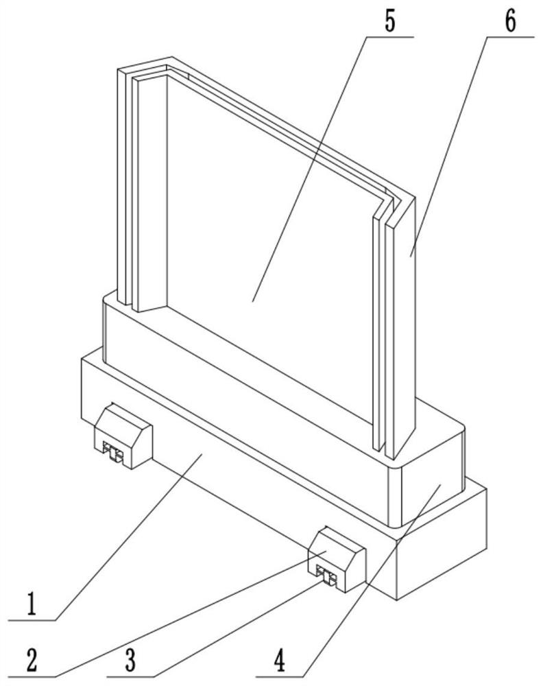
[0030] In order to further illustrate the technical means and effects adopted by the present invention to achieve the predetermined purpose of the invention, the specific embodiments, structures, features and effects of the present invention are described in detail below in conjunction with the accompanying drawings and preferred embodiments.

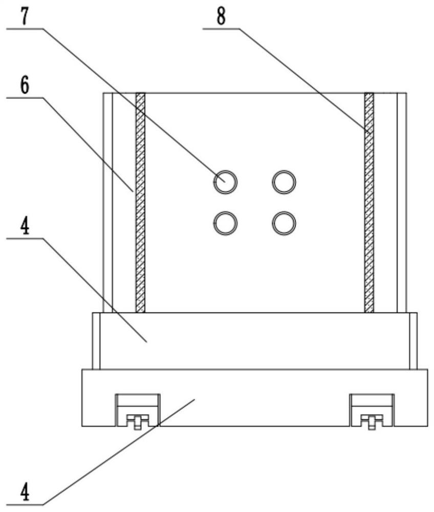
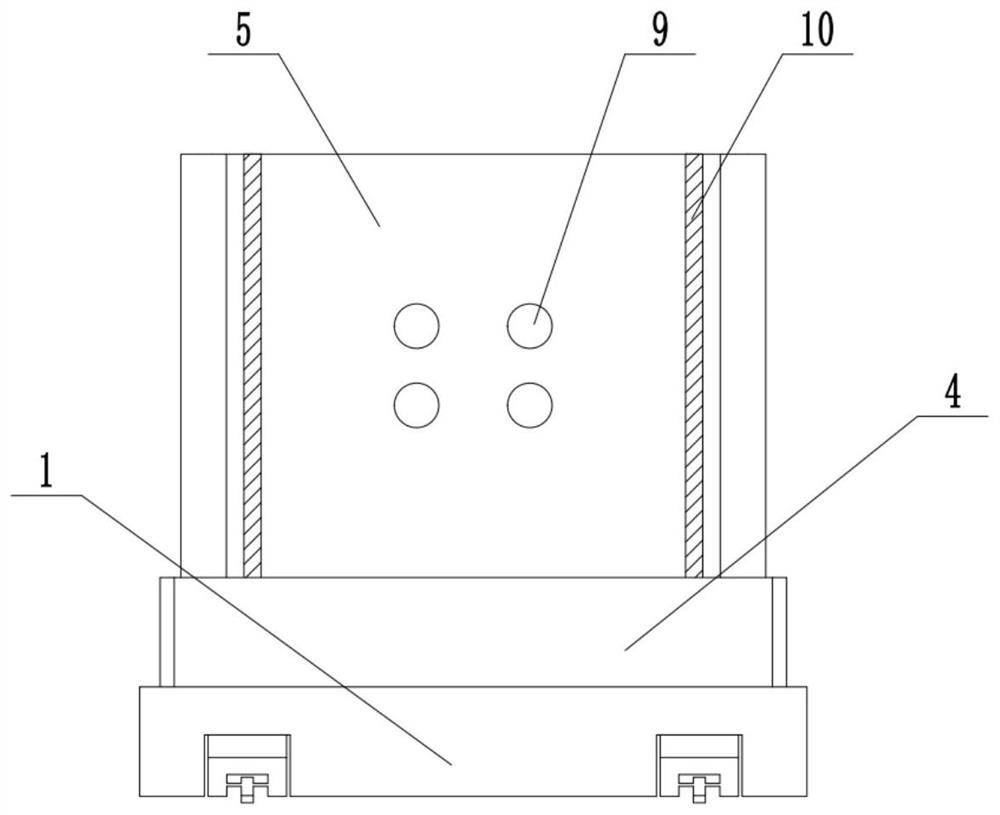
[0031] The reference signs in the drawings include: base 1, placing block 2, electric wheel 3, installation box 4, first bulletproof plate 5, second bulletproof plate 6, spring 7, second magnet strip 8, pressing block 9, First magnet bar 10, mounting block 11, connecting block 12, rotating rod 13, rotating block 14, rack 15, second meshing tooth 16, third meshing tooth 17, mounting boss 18, swing rod 19, generator motor 20 , the fourth meshing tooth 21 .

[0032] example figure 1 , figure 2 , image 3 and Figure 4 shown:

[0033] A movable bulletproof wall comprises a base 1, a mounting box 4 is arranged on the base 1, a first bu...


PUM


Abstract

The invention relates to the technical field of bulletproof walls, and particularly discloses a movable bulletproof wall which comprises a base, a mounting box is arranged on the base, a first bulletproof plate and a second bulletproof plate are arranged on the mounting box, the first bulletproof plate is rotationally connected with the mounting box, and the second bulletproof plate is fixedly connected with the mounting box. A first magnet strip and a second magnet strip which can be magnetically connected are arranged at the corresponding positions of the back face of the first bulletproof plate and the front face of the second bulletproof plate correspondingly, pressing blocks and springs capable of making contact with the pressing blocks are arranged at the corresponding positions of the back face of the first bulletproof plate and the front face of the second bulletproof plate correspondingly, and a rotating rod is rotationally connected into the mounting box. A rotating block is arranged on the rotating rod, a mounting block is arranged at the top of the rotating block, the free end of the mounting block penetrates out of the mounting box to be fixedly connected with a connecting block, the connecting block is connected with the bottom of the first bulletproof plate, and first meshing teeth are arranged on the periphery, except for the mounting block, of the rotating block; the movable bulletproof wall solves the problem that a traditional movable bulletproof wall is low in energy utilization.

Description

technical field [0001] The present application relates to the technical field of bulletproof walls, and specifically discloses a movable bulletproof wall. Background technique [0002] Bulletproof wall refers to a wall with strong protective performance, which can provide a good safety guarantee for the personal safety of key protection targets. In the field of training of relevant personnel, bulletproof walls are generally placed on large and wide shooting ranges for shooting. The training target is determined by the number of bullets shot by the relevant personnel to the bulletproof wall to determine whether the training target is reached; [0003] As mentioned in the background art, in order to ensure the health and safety of people, this kind of bulletproof wall is generally placed in a large and wide shooting range, but for shooting training, the position of the bulletproof wall cannot be static, and the position should be changed. In the existing technology, two forms...

Claims


Application Information

Patent Timeline
IPC IPC(8): F41J9/02F41J7/00F41J1/01F41J1/10
CPCF41J9/02F41J7/00F41J1/01F41J1/10
Inventor 郑义平林海滨陈豪黄小龙刘志艺
Owner 福建泉城特种装备科技有限公司
Learn More